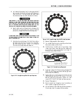
SECTION 3 - CHASSIS & TURNTABLE
3-38
– JLG Lift –
3121290
Disassembly
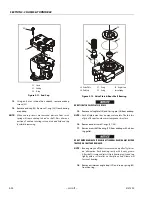
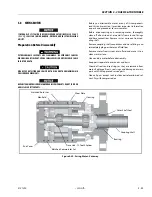
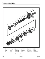
Refer to Figure 3-32., Swing Bearing Drive.
1.
Clean area around swing motor (1) to prevent any dirt
from entering system.
2.
Tag and disconnect hydraulic lines running to swing
motor. Cap or plug all openings.
SECURE WORM GEAR SHAFT SO IT DOES NOT PULL OUT ANY WHEN REMOVING
THE SWING MOTOR. FAILURE TO DO SO COULD DAMAGE WORM GEAR SEALS.
3.
Remove bolts (2) and washers (3) securing swing motor
to swing drive housing (4).
4.
Carefully pull swing motor from housing.
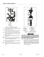
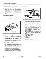
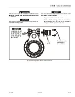
Refer to Figure 3-40., Swing Motor Removal and Installation.
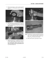
1.
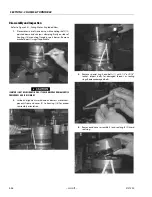
Remove two bolts (5) and washers (6) that hold turnta-
ble bearing (7) to housing (4).
2.
Remove two machine screws (8) on cover plate (9)
immediately in front of pinion (10).
3.
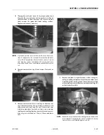
Remove eight cap screws (11) from gear pinion cap (12).
Pry cap from housing. Cover plate (9) will come off with
cap. Note where sealant is on cover and plate so it can
be applied in same location during assembly. Note num-
ber and color of shims (13) between cap and housing.
4.
Remove six small screws (14) from cover plate. Pry cover
plate (9) from cap (12). Discard cover plate. Note number
and color of shims (15) between cover plate and cap.
NOTE:
If there are five screws or drive screws holding cover plate
to cap, a new cap (12) should be ordered. This is an older
version; new cover plate has six holes.
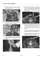
5.
Lift directly up and remove pinion and gear assembly
(10, 16 - 22) from housing (4).
6.
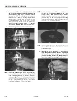
Disassemble pinion and gear assembly using a press.
Support worm gear (20) on press wIth pinion (10) facing
down. Allow room for pinion to be pressed out of gear.
Press pinon out of bearing (22), spacer (21), and worm
gear (20).
7.
Remove face seal (18) and O-ring (19) from face of worm
gear (20). Note how seal is assembled.
8.
Remove bearing (17) and Nilos Ring (16) from pinion (18)
with an external bearing puller or press.
9.
Remove motor adapter (23) and shim (24).
10.
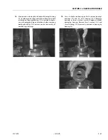
Remove two bolts (25) from worm cap (26). Remove and
discard shims (27) and seal (28).
11.
Remove worm (29) from housing (4) by pushing worm
from motor end using a steel rod and hammer. Use a
soft hammer to tap worm on hex end to remove bearing
(30) from opposite end of housing.
12.
If necessary, remove bearing cup from adapter (23)
using a small pry bar or by welding a small bead of weld
on internal diameter of the cup.
13.
Remove bearing (31) from worm (29) using an external
bearing puller or press.
Summary of Contents for 450A II Series
Page 46: ...SECTION 3 CHASSIS TURNTABLE 3 6 JLG Lift 3121290 Figure 3 4 Drive Hub 4WD Front Only ...
Page 79: ...SECTION 3 CHASSIS TURNTABLE 3121290 JLG Lift 3 39 Figure 3 32 Swing Bearing Drive ...
Page 101: ...SECTION 3 CHASSIS TURNTABLE 3121290 JLG Lift 3 61 Figure 3 42 Auxiliary Pump ...
Page 113: ...SECTION 3 CHASSIS TURNTABLE 3121290 JLG Lift 3 73 Figure 3 53 EMR2 Fault Codes Sheet 1 of 5 ...
Page 114: ...SECTION 3 CHASSIS TURNTABLE 3 74 JLG Lift 3121290 Figure 3 54 EMR2 Fault Codes Sheet 2 of 5 ...
Page 115: ...SECTION 3 CHASSIS TURNTABLE 3121290 JLG Lift 3 75 Figure 3 55 EMR2 Fault Codes Sheet 3 of 5 ...
Page 116: ...SECTION 3 CHASSIS TURNTABLE 3 76 JLG Lift 3121290 Figure 3 56 EMR2 Fault Codes Sheet 4 of 5 ...
Page 117: ...SECTION 3 CHASSIS TURNTABLE 3121290 JLG Lift 3 77 Figure 3 57 EMR2 Fault Codes Sheet 5 of 5 ...
Page 159: ...SECTION 3 CHASSIS TURNTABLE 3121290 JLG Lift 3 119 ...
Page 161: ...SECTION 3 CHASSIS TURNTABLE 3121290 JLG Lift 3 121 ...
Page 163: ...SECTION 3 CHASSIS TURNTABLE 3121290 JLG Lift 3 123 ...
Page 165: ...SECTION 3 CHASSIS TURNTABLE 3121290 JLG Lift 3 125 ...
Page 173: ...SECTION 3 CHASSIS TURNTABLE 3121290 JLG Lift 3 133 Sensor Transducer Type ...
Page 177: ...SECTION 3 CHASSIS TURNTABLE 3121290 JLG Lift 3 137 Sensor Transducer Type ...
Page 179: ...SECTION 3 CHASSIS TURNTABLE 3121290 JLG Lift 3 139 ...
Page 181: ...SECTION 3 CHASSIS TURNTABLE 3121290 JLG Lift 3 141 ...
Page 183: ...SECTION 3 CHASSIS TURNTABLE 3121290 JLG Lift 3 143 ...
Page 185: ...SECTION 3 CHASSIS TURNTABLE 3121290 JLG Lift 3 145 ...
Page 187: ...SECTION 3 CHASSIS TURNTABLE 3121290 JLG Lift 3 147 ...
Page 203: ...SECTION 3 CHASSIS TURNTABLE 3121290 JLG Lift 3 163 ...
Page 207: ...SECTION 3 CHASSIS TURNTABLE 3121290 JLG Lift 3 167 ...
Page 217: ...SECTION 4 BOOM PLATFORM 3121290 JLG Lift 4 5 Figure 4 2 Boom Limit Switches ...
Page 310: ...SECTION 5 HYDRAULICS 5 70 JLG Lift 3121290 NOTES ...
Page 312: ...SECTION 6 JLG CONTROL SYSTEM 6 2 JLG Lift 3121290 Figure 6 2 Controller Block Diagram 0 ...
Page 370: ...SECTION 6 JLG CONTROL SYSTEM 6 60 JLG Lift 3121290 NOTES ...
Page 394: ...SECTION 7 BASIC ELECTRICAL INFORMATION SCHEMATICS 7 24 JLG Lift 3121290 NOTES ...
Page 395: ......

