


SECTION 3 - CHASSIS & TURNTABLE
3-90
– JLG Lift –
3121290
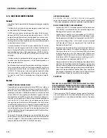
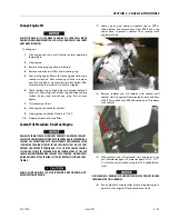
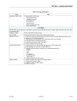
Exhaust System And Catalytic Converter Inspection
And Maintenance
EXHAUST SYSTEM ON THIS EMISSION CERTIFIED ENGINE CONTAINS A HEATED
EXHAUST GAS OXYGEN SENSOR (HEGO) WHICH PROVIDES FEEDBACK TO THE
ECM ON AMOUNT OF OXYGEN PRESENT IN THE EXHAUST STREAM AFTER COM-
BUSTION. OXYGEN IN THE EXHAUST STREAM IS MEASURED IN VOLTAGE AND
SENT TO THE ECM. THE ECM THEN MAKES CORRECTIONS TO THE FUEL AIR
RATIO TO ENSURE PROPER FUEL CHARGE AND OPTIMUM CATALYTIC PERFOR-
MANCE. EXHAUST CONNECTIONS MUST REMAIN SECURE AND AIR TIGHT.
THE HEGO SENSOR IS SENSITIVE TO SILICONE BASED PRODUCTS. DO NOT USE
SILICONE SPRAYS OR HOSES WHICH ARE ASSEMBLED USING SILICONE LUBRI-
CANTS. SILICONE CONTAMINATION CAN CAUSE SEVERE DAMAGE TO THE
HEGO.
1.
Check exhaust manifold at cylinder head for leaks and
all retaining bolts and shields (if used) are in place.
2.
Check manifold to exhaust pipe fasteners are tight and
there are no exhaust leaks. Repair if necessary.
3.
Inspect HEGO electrical connector is seated and locked.
Check wires for cracking, splits, chafing or “burn
through.” Repair if necessary.
4.
Check exhaust pipe extension connector for leaks.
Tighten if necessary.
5.
Check catalyst muffler is securely mounted. Check for
leaks at inlet and outlet.
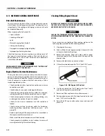
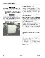
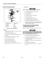
Temperature Manifold Absolute Pressure (TMAP)
Sensor
NOTE:
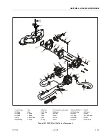
Refer to Figure 3-59. GM 3.0 Dual Fuel System Components.
REMOVAL
1.
Disconnect TMAP (402) electrical connector.
2.
Remove retaining bolt (403), washer (404), and TMAP
(402).
INSTALLATION
NOTE:
Apply a small amount of O-ring lubricant before installa-
tion.
1.
Install TMAP (402). Secure with washer (404) and bolt
(403).
2.
Torque retaining bolt to 62 in-lb (7 Nm).
3.
Start vehicle and check for proper operation.
Throttle Body (ETC) Replacement
NOTE:
Refer to Figure 3-59. GM 3.0 Dual Fuel System Components.
REMOVAL
1.
Disconnect negative battery cable.
2.
Remove Mixer (See “Mixer Replacement” on page 90).
3.
Disconnect TMAP electrical connector.
4.
Disconnect electronic throttle control connector.
5.
Remove bolts (208), adapter (204), and throttle body
(201) from manifold.
6.
Remove spacer (205).
7.
Remove and discard gasket (202) and O-ring (203).
INSTALLATION
NOTE:
Lightly lubricate O-ring.
1.
Install O-ring (203) and spacer (205) on throttle body
(201).
2.
Align new gasket (202) and throttle body on manifold.
3.
Slide adapter (204) on throttle body and secure with
four bolts (208).
4.
Reinstall Mixer (See “Mixer Replacement” on page 90).
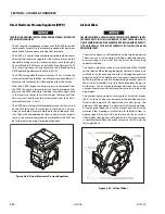
Mixer Replacement
NOTE:
Refer to Figure 3-59. GM 3.0 Dual Fuel System Components.
REMOVAL
1.
Remove EPR. (See “Electronic Pressure Regulator (EPR)
Replacement” on page 91)
2.
Remove Air Intake hose from Mixer.
3.
Remove four bolts (206) and washers (207) securing
mixer (104) to adapter (204). Remove Mixer.
INSTALLATION
COVER THROTTLE BODY ADAPTER OPENING TO PREVENT DEBRIS FROM
ENTERING ENGINE.
1.
Install Mixer (104) to Adapter (204). Secure with four
washers (207) and bolts (206). Torque to 80 in-lb (9 Nm)
2.
Install EPR (See “Electronic Pressure Regulator (EPR)
Replacement” on page 91).
3.
Reinstall Air Intake Hose.
4.
Start engine and leak check all fittings and connections.
Summary of Contents for 450A II Series
Page 46: ...SECTION 3 CHASSIS TURNTABLE 3 6 JLG Lift 3121290 Figure 3 4 Drive Hub 4WD Front Only ...
Page 79: ...SECTION 3 CHASSIS TURNTABLE 3121290 JLG Lift 3 39 Figure 3 32 Swing Bearing Drive ...
Page 101: ...SECTION 3 CHASSIS TURNTABLE 3121290 JLG Lift 3 61 Figure 3 42 Auxiliary Pump ...
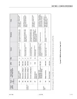
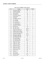
Page 113: ...SECTION 3 CHASSIS TURNTABLE 3121290 JLG Lift 3 73 Figure 3 53 EMR2 Fault Codes Sheet 1 of 5 ...
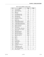
Page 114: ...SECTION 3 CHASSIS TURNTABLE 3 74 JLG Lift 3121290 Figure 3 54 EMR2 Fault Codes Sheet 2 of 5 ...
Page 115: ...SECTION 3 CHASSIS TURNTABLE 3121290 JLG Lift 3 75 Figure 3 55 EMR2 Fault Codes Sheet 3 of 5 ...
Page 116: ...SECTION 3 CHASSIS TURNTABLE 3 76 JLG Lift 3121290 Figure 3 56 EMR2 Fault Codes Sheet 4 of 5 ...
Page 117: ...SECTION 3 CHASSIS TURNTABLE 3121290 JLG Lift 3 77 Figure 3 57 EMR2 Fault Codes Sheet 5 of 5 ...
Page 159: ...SECTION 3 CHASSIS TURNTABLE 3121290 JLG Lift 3 119 ...
Page 161: ...SECTION 3 CHASSIS TURNTABLE 3121290 JLG Lift 3 121 ...
Page 163: ...SECTION 3 CHASSIS TURNTABLE 3121290 JLG Lift 3 123 ...
Page 165: ...SECTION 3 CHASSIS TURNTABLE 3121290 JLG Lift 3 125 ...
Page 173: ...SECTION 3 CHASSIS TURNTABLE 3121290 JLG Lift 3 133 Sensor Transducer Type ...
Page 177: ...SECTION 3 CHASSIS TURNTABLE 3121290 JLG Lift 3 137 Sensor Transducer Type ...
Page 179: ...SECTION 3 CHASSIS TURNTABLE 3121290 JLG Lift 3 139 ...
Page 181: ...SECTION 3 CHASSIS TURNTABLE 3121290 JLG Lift 3 141 ...
Page 183: ...SECTION 3 CHASSIS TURNTABLE 3121290 JLG Lift 3 143 ...
Page 185: ...SECTION 3 CHASSIS TURNTABLE 3121290 JLG Lift 3 145 ...
Page 187: ...SECTION 3 CHASSIS TURNTABLE 3121290 JLG Lift 3 147 ...
Page 203: ...SECTION 3 CHASSIS TURNTABLE 3121290 JLG Lift 3 163 ...
Page 207: ...SECTION 3 CHASSIS TURNTABLE 3121290 JLG Lift 3 167 ...
Page 217: ...SECTION 4 BOOM PLATFORM 3121290 JLG Lift 4 5 Figure 4 2 Boom Limit Switches ...
Page 310: ...SECTION 5 HYDRAULICS 5 70 JLG Lift 3121290 NOTES ...
Page 312: ...SECTION 6 JLG CONTROL SYSTEM 6 2 JLG Lift 3121290 Figure 6 2 Controller Block Diagram 0 ...
Page 370: ...SECTION 6 JLG CONTROL SYSTEM 6 60 JLG Lift 3121290 NOTES ...
Page 394: ...SECTION 7 BASIC ELECTRICAL INFORMATION SCHEMATICS 7 24 JLG Lift 3121290 NOTES ...
Page 395: ......


