SECTION 4 - BOOM & PLATFORM
4-2
– JLG Lift –
3121290
Main Boom Disassembly
1.
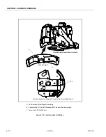
Loosen jam nuts on aft end of fly boom wear pad adjust-
ment and loosen adjustments.
2.
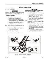
Using a portable power source, attach hose to telescope
cylinder port block. Using all applicable safety precau-
tions, activate hydraulic system and extend cylinder to
gain access to cylinder rod retaining pin. Shut down
hydraulic system.
3.
Carefully disconnect hydraulic hose from retract port of
cylinder. There will be initial weeping of hydraulic fluid
which can be caught in a suitable container. After initial
discharge, there should be no further leakage from the
retract port.
4.
Remove hardware securing telescope cylinder to the fly
boom section, then remove pin from fly.
5.
Remove hardware securing telescope cylinder to the
base boom section.
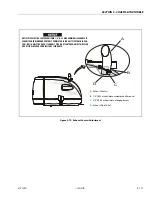
WHEN REMOVING TELESCOPE C YLINDER FROM BOOM SECTIONS. CARE
SHOULD BE TAKEN NOT TO LEAVE CYLINDER REST ON POWERTRACK WHICH
COULD CAUSE DAMAGE TO POWERTRACK.
6.
Using a suitable lifting device, remove telescope cylin-
der from boom sections.
7.
Using a piece of tape, mark length of hoses and wires
from front of fly boom and bottom of base boom for
reassembly.
8.
Remove hardware securing front wear pads on base
boom section. Remove wear pads.
9.
Remove hardware securing powertrack to aft end of fly
boom section.
10.
Using a suitable lifting device, remove fly boom from
boom section.
11.
Remove hydraulic lines and electrical cables from pow-
ertrack.
12.
Remove hardware securing powertrack to base boom
section. Remove powertrack.
Inspection
1.
Inspect all boom pivot pins for wear, scoring or other
damage, and tapering or ovality. Replace pins as
needed.
2.
Inspect lift cylinder pins for wear, scoring or other dam-
age, and for tapering or ovality. Ensure pin surfaces are
protected prior to installation. Replace pins as needed.
3.
Inspect telescope cylinder rod attach pin for wear, scor-
ing or other damage. Replace pin as needed.
4.
Inspect inner diameter of boom pivot bushings for scor-
ing, distortion, wear or other damage. Replace bushings
as needed.
5.
Inspect wear pads for wear.
6.
Inspect all threaded components for damage such as
stretching, thread deformation, or twisting. Replace as
needed.
7.
Inspect structural units of boom assembly for bending,
cracking, separation of welds, or other damage. Replace
boom sections as needed.
Summary of Contents for 450A II Series
Page 46: ...SECTION 3 CHASSIS TURNTABLE 3 6 JLG Lift 3121290 Figure 3 4 Drive Hub 4WD Front Only ...
Page 79: ...SECTION 3 CHASSIS TURNTABLE 3121290 JLG Lift 3 39 Figure 3 32 Swing Bearing Drive ...
Page 101: ...SECTION 3 CHASSIS TURNTABLE 3121290 JLG Lift 3 61 Figure 3 42 Auxiliary Pump ...
Page 113: ...SECTION 3 CHASSIS TURNTABLE 3121290 JLG Lift 3 73 Figure 3 53 EMR2 Fault Codes Sheet 1 of 5 ...
Page 114: ...SECTION 3 CHASSIS TURNTABLE 3 74 JLG Lift 3121290 Figure 3 54 EMR2 Fault Codes Sheet 2 of 5 ...
Page 115: ...SECTION 3 CHASSIS TURNTABLE 3121290 JLG Lift 3 75 Figure 3 55 EMR2 Fault Codes Sheet 3 of 5 ...
Page 116: ...SECTION 3 CHASSIS TURNTABLE 3 76 JLG Lift 3121290 Figure 3 56 EMR2 Fault Codes Sheet 4 of 5 ...
Page 117: ...SECTION 3 CHASSIS TURNTABLE 3121290 JLG Lift 3 77 Figure 3 57 EMR2 Fault Codes Sheet 5 of 5 ...
Page 159: ...SECTION 3 CHASSIS TURNTABLE 3121290 JLG Lift 3 119 ...
Page 161: ...SECTION 3 CHASSIS TURNTABLE 3121290 JLG Lift 3 121 ...
Page 163: ...SECTION 3 CHASSIS TURNTABLE 3121290 JLG Lift 3 123 ...
Page 165: ...SECTION 3 CHASSIS TURNTABLE 3121290 JLG Lift 3 125 ...
Page 173: ...SECTION 3 CHASSIS TURNTABLE 3121290 JLG Lift 3 133 Sensor Transducer Type ...
Page 177: ...SECTION 3 CHASSIS TURNTABLE 3121290 JLG Lift 3 137 Sensor Transducer Type ...
Page 179: ...SECTION 3 CHASSIS TURNTABLE 3121290 JLG Lift 3 139 ...
Page 181: ...SECTION 3 CHASSIS TURNTABLE 3121290 JLG Lift 3 141 ...
Page 183: ...SECTION 3 CHASSIS TURNTABLE 3121290 JLG Lift 3 143 ...
Page 185: ...SECTION 3 CHASSIS TURNTABLE 3121290 JLG Lift 3 145 ...
Page 187: ...SECTION 3 CHASSIS TURNTABLE 3121290 JLG Lift 3 147 ...
Page 203: ...SECTION 3 CHASSIS TURNTABLE 3121290 JLG Lift 3 163 ...
Page 207: ...SECTION 3 CHASSIS TURNTABLE 3121290 JLG Lift 3 167 ...
Page 217: ...SECTION 4 BOOM PLATFORM 3121290 JLG Lift 4 5 Figure 4 2 Boom Limit Switches ...
Page 310: ...SECTION 5 HYDRAULICS 5 70 JLG Lift 3121290 NOTES ...
Page 312: ...SECTION 6 JLG CONTROL SYSTEM 6 2 JLG Lift 3121290 Figure 6 2 Controller Block Diagram 0 ...
Page 370: ...SECTION 6 JLG CONTROL SYSTEM 6 60 JLG Lift 3121290 NOTES ...
Page 394: ...SECTION 7 BASIC ELECTRICAL INFORMATION SCHEMATICS 7 24 JLG Lift 3121290 NOTES ...
Page 395: ......

