


SECTION 5 - HYDRAULICS
3121290
– JLG Lift –
5-65
Charge Pump
NOTE:
Disassemble charge pump to inspect and clean, or change
auxiliary shaft drive coupling.
1.
Remove auxiliary pump if necessary.
2.
Remove screws retaining charge pump cover to pump
housing (Torx T). Seven screws are used with “no pad” or
SAE “A” auxiliary mounting pad charge pump cover, and
six screws are used with SAE “B” auxiliary mounting pad
charge pump cover. Remove charge pump cover, gas-
ket, and cover locating pins.
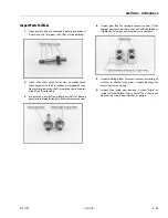
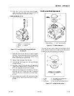
3.
Remove gerotor cover assembly from charge pump
cover or back of pump housing. Remove gerotor cover
O-rings. Two O-rings are used on gerotor cover of all
pumps.
4.
Remove gerotor assembly from gerotor cover or pump
housing.
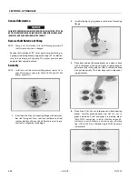
5.
Remove gerotor drive pin and drive coupling. Remove
gerotor cover locating pin from pump housing.
6.
Inspect each part if they are to be reused. If either gerotor
assembly parts needs to be replaced, they must both be
replaced. Always replace O-rings and charge pump cover
gasket. Inspect journal bearing in gerotor cover for exces-
sive wear.
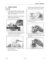
7.
Lubricate gerotor assembly with clean hydraulic oil
before assembly.
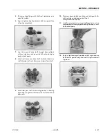
8.
Install gerotor drive pin into hole in drive coupling.
Apply grease or petroleum jelly to keep in place.
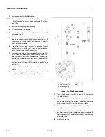
9.
Install drive coupling on pump shaft with smaller out-
side diameter facing away from shaft.
10.
Install gerotor assembly onto coupling.
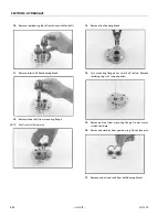
11.
Install gerotor cover locating pin into pump housing.
Install gerotor cover assembly over gerotor. Locating pin
must engage slot in gerotor cover.
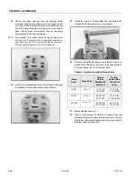
NOTE:
Charge pump rotation is determined by location of gerotor
recess and pressure balance hole in gerotor cover. Different
gerotor covers are used for clockwise and counterclockwise
rotation pumps.
12.
Install new pressure balance O-rings to gerotor cover
and retain with petroleum jelly or grease.
13.
Install charge pump cover locating pins and new charge
pump cover gasket.
14.
Install charge pump cover. Cover must engage gerotor
cover and locating pins. Install charge pump cover
screws. Torque evenly to 26 - 32 ft-lb (36-43 Nm).
15.
Reinstall auxiliary pump if necessary.
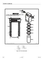
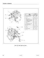
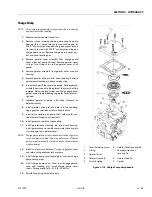
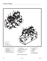
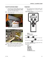
Figure 5-114. Charge Pump Components
1.
Cover Retaining Screw
6.
Geroter Cover Locating Pin
2.
O-Ring
7.
Charge Pump Cover
Locating Pin
3.
Geroter Cover
4.
Geroter Assembly
8.
Geroter Drive Pin
5.
Drive Coupling
9.
Gasket
Summary of Contents for 450A II Series
Page 46: ...SECTION 3 CHASSIS TURNTABLE 3 6 JLG Lift 3121290 Figure 3 4 Drive Hub 4WD Front Only ...
Page 79: ...SECTION 3 CHASSIS TURNTABLE 3121290 JLG Lift 3 39 Figure 3 32 Swing Bearing Drive ...
Page 101: ...SECTION 3 CHASSIS TURNTABLE 3121290 JLG Lift 3 61 Figure 3 42 Auxiliary Pump ...
Page 113: ...SECTION 3 CHASSIS TURNTABLE 3121290 JLG Lift 3 73 Figure 3 53 EMR2 Fault Codes Sheet 1 of 5 ...
Page 114: ...SECTION 3 CHASSIS TURNTABLE 3 74 JLG Lift 3121290 Figure 3 54 EMR2 Fault Codes Sheet 2 of 5 ...
Page 115: ...SECTION 3 CHASSIS TURNTABLE 3121290 JLG Lift 3 75 Figure 3 55 EMR2 Fault Codes Sheet 3 of 5 ...
Page 116: ...SECTION 3 CHASSIS TURNTABLE 3 76 JLG Lift 3121290 Figure 3 56 EMR2 Fault Codes Sheet 4 of 5 ...
Page 117: ...SECTION 3 CHASSIS TURNTABLE 3121290 JLG Lift 3 77 Figure 3 57 EMR2 Fault Codes Sheet 5 of 5 ...
Page 159: ...SECTION 3 CHASSIS TURNTABLE 3121290 JLG Lift 3 119 ...
Page 161: ...SECTION 3 CHASSIS TURNTABLE 3121290 JLG Lift 3 121 ...
Page 163: ...SECTION 3 CHASSIS TURNTABLE 3121290 JLG Lift 3 123 ...
Page 165: ...SECTION 3 CHASSIS TURNTABLE 3121290 JLG Lift 3 125 ...
Page 173: ...SECTION 3 CHASSIS TURNTABLE 3121290 JLG Lift 3 133 Sensor Transducer Type ...
Page 177: ...SECTION 3 CHASSIS TURNTABLE 3121290 JLG Lift 3 137 Sensor Transducer Type ...
Page 179: ...SECTION 3 CHASSIS TURNTABLE 3121290 JLG Lift 3 139 ...
Page 181: ...SECTION 3 CHASSIS TURNTABLE 3121290 JLG Lift 3 141 ...
Page 183: ...SECTION 3 CHASSIS TURNTABLE 3121290 JLG Lift 3 143 ...
Page 185: ...SECTION 3 CHASSIS TURNTABLE 3121290 JLG Lift 3 145 ...
Page 187: ...SECTION 3 CHASSIS TURNTABLE 3121290 JLG Lift 3 147 ...
Page 203: ...SECTION 3 CHASSIS TURNTABLE 3121290 JLG Lift 3 163 ...
Page 207: ...SECTION 3 CHASSIS TURNTABLE 3121290 JLG Lift 3 167 ...
Page 217: ...SECTION 4 BOOM PLATFORM 3121290 JLG Lift 4 5 Figure 4 2 Boom Limit Switches ...
Page 310: ...SECTION 5 HYDRAULICS 5 70 JLG Lift 3121290 NOTES ...
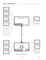
Page 312: ...SECTION 6 JLG CONTROL SYSTEM 6 2 JLG Lift 3121290 Figure 6 2 Controller Block Diagram 0 ...
Page 370: ...SECTION 6 JLG CONTROL SYSTEM 6 60 JLG Lift 3121290 NOTES ...
Page 394: ...SECTION 7 BASIC ELECTRICAL INFORMATION SCHEMATICS 7 24 JLG Lift 3121290 NOTES ...
Page 395: ......


