SECTION 3 - CHASSIS & TURNTABLE
3121290
– JLG Lift –
3-41
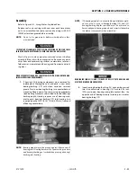
5.
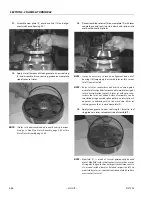
Use suitable lift equipment and install bearing/rotation
box assembly to frame with soft spot (red) 90 degree rel-
ative to load axis. If reusing old bearing, align scribed
line of outer bearing race with scribed mark on frame.
SWING BEARING IS THE ONLY STRUCTURAL LINK BETWEEN FRAME AND
TURNTABLE. JLG INDUSTRIES RECOMMENDS ALL REMOVED GRADE 8 BEAR-
ING NUTS AND BOLTS BE DISCARDED AND REPLACED WITH NEW NUTS AND
BOLTS. IT IS IMPERATIVE THAT REPLACEMENT HARDWARE MEETS JLG SPECI-
FICATIONS. USE OF GENUINE JLG HARDWARE IS HIGHLY RECOMMENDED.
6.
Apply a light coating of thread locking compound JLG
PN 0100019 to new bearing bolts. Loosely install bolts
and washers through frame and outer bearing race.
IF COMPRESSED AIR OR ELECTRICALLY OPERATED IMPACT WRENCH IS USED
TO TIGHTEN BEARING ATTACHMENT BOLTS, CHECK TORQUE SETTING ACCU-
RACY OF TOOL BEFORE USE.
7.
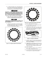
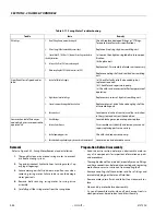
Tighten bolts to initial torque of 130 ft-lb (176 Nm) follow-
ing torque sequence shown in Figure 3-34., Swing Bear-
ing (Dohi) Torque Sequence. Tighten to final torque of
190 ft-lb (257 Nm) following same sequence.
Figure 3-34. Swing Bearing (Dohi) Torque Sequence
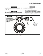
Figure 3-35. Swing Bearing (Jing Wei) Torque Sequence
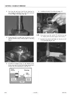
8.
Remove lifting equipment from bearing.
9.
Use suitable lift equipment to carefully position turnta-
ble assembly above machine frame.
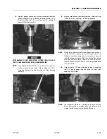
10.
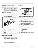
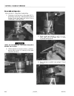
Carefully lower turntable onto swing bearing. Align
scribed line of inner race of bearing with scribed mark
on turntable. If a new swing bearing is used, align 1/8"
NPT holes with notches in frame.
Figure 3-36. Swing Bearing Alignment
11.
Apply light coating of JLG Thread Locking Compound PN
0100019 to new bearing bolts and install through turnta-
ble and inner race of bearing.
12.
Tighten bolts to an initial torque of 130 ft-lb (176 Nm)
following torque sequence shown in Figure 3-34., Swing
Bearing (Dohi) Torque Sequence. Tighten to a final
torque of 190 ft-lb (257 Nm) following same sequence.
13.
Remove lift equipment.
14.
Route hydraulic lines through center of turntable and
frame. Connect as tagged prior to removal.
15.
Activate hydraulic system following all safety precautions.
Check swing system for proper and safe operation.
3
7
21
17
13
9
5
1
24
20
16
12
22
14
10
6
2
23
19
15
11
8
4
17
13
9
5
1
16
12
18
14
10
6
2
15
7
3
11
8
4
18
1
5
1
5
7
9
13
3
17
21
9
13
17
3
7
11
15
19
11
23
20
16
12
8
4
22
18
14
10
6
2
15
16
12
8
4
18
14
10
6
2
Install bearing 1/8 in. NPT holes
aligned with notches in frame.
Summary of Contents for 450A II Series
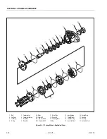
Page 46: ...SECTION 3 CHASSIS TURNTABLE 3 6 JLG Lift 3121290 Figure 3 4 Drive Hub 4WD Front Only ...
Page 79: ...SECTION 3 CHASSIS TURNTABLE 3121290 JLG Lift 3 39 Figure 3 32 Swing Bearing Drive ...
Page 101: ...SECTION 3 CHASSIS TURNTABLE 3121290 JLG Lift 3 61 Figure 3 42 Auxiliary Pump ...
Page 113: ...SECTION 3 CHASSIS TURNTABLE 3121290 JLG Lift 3 73 Figure 3 53 EMR2 Fault Codes Sheet 1 of 5 ...
Page 114: ...SECTION 3 CHASSIS TURNTABLE 3 74 JLG Lift 3121290 Figure 3 54 EMR2 Fault Codes Sheet 2 of 5 ...
Page 115: ...SECTION 3 CHASSIS TURNTABLE 3121290 JLG Lift 3 75 Figure 3 55 EMR2 Fault Codes Sheet 3 of 5 ...
Page 116: ...SECTION 3 CHASSIS TURNTABLE 3 76 JLG Lift 3121290 Figure 3 56 EMR2 Fault Codes Sheet 4 of 5 ...
Page 117: ...SECTION 3 CHASSIS TURNTABLE 3121290 JLG Lift 3 77 Figure 3 57 EMR2 Fault Codes Sheet 5 of 5 ...
Page 159: ...SECTION 3 CHASSIS TURNTABLE 3121290 JLG Lift 3 119 ...
Page 161: ...SECTION 3 CHASSIS TURNTABLE 3121290 JLG Lift 3 121 ...
Page 163: ...SECTION 3 CHASSIS TURNTABLE 3121290 JLG Lift 3 123 ...
Page 165: ...SECTION 3 CHASSIS TURNTABLE 3121290 JLG Lift 3 125 ...
Page 173: ...SECTION 3 CHASSIS TURNTABLE 3121290 JLG Lift 3 133 Sensor Transducer Type ...
Page 177: ...SECTION 3 CHASSIS TURNTABLE 3121290 JLG Lift 3 137 Sensor Transducer Type ...
Page 179: ...SECTION 3 CHASSIS TURNTABLE 3121290 JLG Lift 3 139 ...
Page 181: ...SECTION 3 CHASSIS TURNTABLE 3121290 JLG Lift 3 141 ...
Page 183: ...SECTION 3 CHASSIS TURNTABLE 3121290 JLG Lift 3 143 ...
Page 185: ...SECTION 3 CHASSIS TURNTABLE 3121290 JLG Lift 3 145 ...
Page 187: ...SECTION 3 CHASSIS TURNTABLE 3121290 JLG Lift 3 147 ...
Page 203: ...SECTION 3 CHASSIS TURNTABLE 3121290 JLG Lift 3 163 ...
Page 207: ...SECTION 3 CHASSIS TURNTABLE 3121290 JLG Lift 3 167 ...
Page 217: ...SECTION 4 BOOM PLATFORM 3121290 JLG Lift 4 5 Figure 4 2 Boom Limit Switches ...
Page 310: ...SECTION 5 HYDRAULICS 5 70 JLG Lift 3121290 NOTES ...
Page 312: ...SECTION 6 JLG CONTROL SYSTEM 6 2 JLG Lift 3121290 Figure 6 2 Controller Block Diagram 0 ...
Page 370: ...SECTION 6 JLG CONTROL SYSTEM 6 60 JLG Lift 3121290 NOTES ...
Page 394: ...SECTION 7 BASIC ELECTRICAL INFORMATION SCHEMATICS 7 24 JLG Lift 3121290 NOTES ...
Page 395: ......

