

SECTION 5 - HYDRAULICS
3121290
– JLG Lift –
5-59
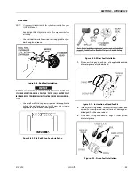
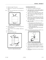
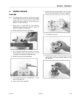
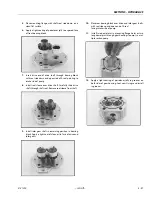
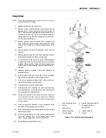
Placing Pump Back Into Service
1.
If shop test stand is available, use
the following proce-
dure for testing rebuilt pumps:
a. Mount pump on test stand. Make sure proper level
of clean oil is available in reservoir. Check suction
line for leaks and obstructions.
b. Start pump and run for three minutes at zero pres-
sure.
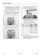
c. Intermittently load pump to 500 P.S.I. for three min-
utes.
d. Intermittently load pump to 1000 P.S.I. for three
minutes.
e. Intermittently load pump to 2000 P.S.I. for three
minutes.
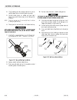
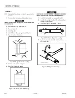
f.
Remove pump from test stand and check for free-
ness of drive shaft. Check pump for signs of external
leakage.
2.
If shop test stand is not available, use
the following proce-
dure for testing rebuilt pumps:
a.
For engine driven pumps,
mount pump on equip-
ment and run pump at 1/2 engine speed at zero
pressure for three minutes.
b. Operate control valve and build pressure intermit-
tently for three minutes.
c. Increase engine speed to full throttle and build
pressure intermittently for three minutes.
d. Stop engine and check pump for external leaks.
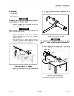
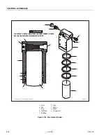
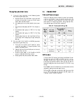
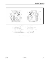
5.4
VARIABLE PUMP
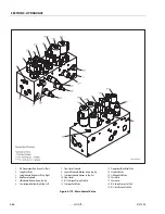
Ports and Pressure Gauges
Proper servicing of pumps and motors requires pressure mea-
sured and monitored at various hydraulic circuit points. The
Series 42 pump has several locations at which to take these
measurements. The following outlines show gauge port loca-
tions, and gauge and fitting size for each port.
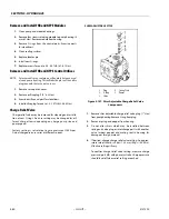
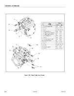
NFPE Control
The 3-position FNR control, and electric and hydraulic non-
feedback proportional (NFPE and NFPH) controls are non-
feedback type controls. FNR and NFPE controls consist of
pump housing mounted modules. Hydraulic input for NFPH is
received through ports on top of pump [9/16–18 SAE O-ring
fitting].
Non-feedback controls are factory set. Control modules can be
removed to clean ports and change O-rings.
FNR and NFPE orifice plugs are located inside the servo piston
covers. NFPH orifice plugs are located in the NFPH ports. Ori-
fice plugs may be cleaned or replaced.
Table 5-2. Recommended Gauge Size
Gauge
Port
Name
Pressure
Measured
Recommended
Gauge Size
Fitting
PSI
Bar
M1 &
M2
System
Pressure
Ports A & B
10000
600
9/16-18
ORF
M3
Charge
1000
60
3/4-16
ORF
M4 &
M5
Servo
1000
60
9/16-18
ORF
L1 & L2
Case
500
35
1-1/16-12
ORF
S
Charge Pump
Inlet Vacuum
30 in. Hg
Vac.
1
1-1/16-12
ORF
Summary of Contents for 450A II Series
Page 46: ...SECTION 3 CHASSIS TURNTABLE 3 6 JLG Lift 3121290 Figure 3 4 Drive Hub 4WD Front Only ...
Page 79: ...SECTION 3 CHASSIS TURNTABLE 3121290 JLG Lift 3 39 Figure 3 32 Swing Bearing Drive ...
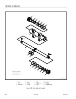
Page 101: ...SECTION 3 CHASSIS TURNTABLE 3121290 JLG Lift 3 61 Figure 3 42 Auxiliary Pump ...
Page 113: ...SECTION 3 CHASSIS TURNTABLE 3121290 JLG Lift 3 73 Figure 3 53 EMR2 Fault Codes Sheet 1 of 5 ...
Page 114: ...SECTION 3 CHASSIS TURNTABLE 3 74 JLG Lift 3121290 Figure 3 54 EMR2 Fault Codes Sheet 2 of 5 ...
Page 115: ...SECTION 3 CHASSIS TURNTABLE 3121290 JLG Lift 3 75 Figure 3 55 EMR2 Fault Codes Sheet 3 of 5 ...
Page 116: ...SECTION 3 CHASSIS TURNTABLE 3 76 JLG Lift 3121290 Figure 3 56 EMR2 Fault Codes Sheet 4 of 5 ...
Page 117: ...SECTION 3 CHASSIS TURNTABLE 3121290 JLG Lift 3 77 Figure 3 57 EMR2 Fault Codes Sheet 5 of 5 ...
Page 159: ...SECTION 3 CHASSIS TURNTABLE 3121290 JLG Lift 3 119 ...
Page 161: ...SECTION 3 CHASSIS TURNTABLE 3121290 JLG Lift 3 121 ...
Page 163: ...SECTION 3 CHASSIS TURNTABLE 3121290 JLG Lift 3 123 ...
Page 165: ...SECTION 3 CHASSIS TURNTABLE 3121290 JLG Lift 3 125 ...
Page 173: ...SECTION 3 CHASSIS TURNTABLE 3121290 JLG Lift 3 133 Sensor Transducer Type ...
Page 177: ...SECTION 3 CHASSIS TURNTABLE 3121290 JLG Lift 3 137 Sensor Transducer Type ...
Page 179: ...SECTION 3 CHASSIS TURNTABLE 3121290 JLG Lift 3 139 ...
Page 181: ...SECTION 3 CHASSIS TURNTABLE 3121290 JLG Lift 3 141 ...
Page 183: ...SECTION 3 CHASSIS TURNTABLE 3121290 JLG Lift 3 143 ...
Page 185: ...SECTION 3 CHASSIS TURNTABLE 3121290 JLG Lift 3 145 ...
Page 187: ...SECTION 3 CHASSIS TURNTABLE 3121290 JLG Lift 3 147 ...
Page 203: ...SECTION 3 CHASSIS TURNTABLE 3121290 JLG Lift 3 163 ...
Page 207: ...SECTION 3 CHASSIS TURNTABLE 3121290 JLG Lift 3 167 ...
Page 217: ...SECTION 4 BOOM PLATFORM 3121290 JLG Lift 4 5 Figure 4 2 Boom Limit Switches ...
Page 310: ...SECTION 5 HYDRAULICS 5 70 JLG Lift 3121290 NOTES ...
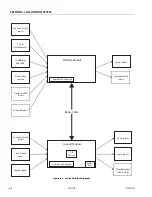
Page 312: ...SECTION 6 JLG CONTROL SYSTEM 6 2 JLG Lift 3121290 Figure 6 2 Controller Block Diagram 0 ...
Page 370: ...SECTION 6 JLG CONTROL SYSTEM 6 60 JLG Lift 3121290 NOTES ...
Page 394: ...SECTION 7 BASIC ELECTRICAL INFORMATION SCHEMATICS 7 24 JLG Lift 3121290 NOTES ...
Page 395: ......


