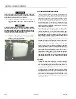
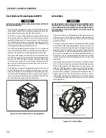


SECTION 3 - CHASSIS & TURNTABLE
3-96
– JLG Lift –
3121290
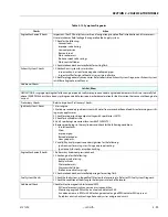
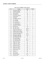
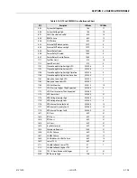
Table 3-13. Symptom Diagnosis
Checks
Action
Important Preliminary Checks
Before Using This Section
Before using this section, you should have performed On Board Diagnostic Check and determined that:
1. The Control Module and MIL (Malfunction Indicator Lamp) are operating correctly.
2. There are no Diagnostic Trouble Codes (DTCs) stored, or a DTC exists but without a MIL.
Several of the following symptom procedures call for a careful visual and physical check. Visual and phys-
ical checks are very important. These checks can lead to correcting a problem without further checks that
may save valuable time.
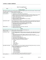
LPG Fuel System Check
1. Verify customer complaint.
2. Locate correct symptom table.
3. Check items indicated under that symptom.
4. Operate vehicle under conditions the symptom occurs. Verify HEGO switching between lean and rich.
IMPORTANT! Normal HEGO switching indicates the LPG fuel system is in closed loop and operat-
ing correctly at that time.
Visual and Physical Checks
1. Check all ECM system fuses and circuit breakers.
2. Check the ECM ground for being clean, tight and in its proper location.
3. Check the vacuum hoses for splits, kinks and proper connections.
4. Check thoroughly for any type of leak or restriction.
5. Check for air leaks at all mounting areas of intake manifold sealing surfaces.
6. Check for proper installation of the mixer module assembly.
7. Check for air leaks at mixer assembly.
8. Check ignition wires for the following conditions:
- Cracking
- Hardness
- Proper routing
- Carbon tracking
9. Check wiring for the following items:
- Proper connections, pinches or cuts.
The following symptom tables contain groups of possible causes for each symptom. The order of these
procedures is not important. If scan tool readings do not indicate problems, proceed in a logical order,
easiest to check or most likely to cause first.
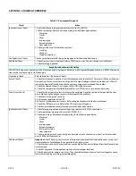
Intermittent
DEFINITION: The problem may or may not turn ON the Malfunction Indicator Lamp (MIL) or store a Diagnostic Trouble Code (DTC).
Preliminary Checks
Refer to Important Preliminary Checks. Do not use DTC tables. If a fault is intermittent, use of DTC tables
may result in replacement of good parts.
Faulty Electrical Connections
or Wiring
Faulty electrical connections or wiring can cause most intermittent problems.
1. Check suspected circuit for the following conditions:
- Faulty fuse or circuit breaker
- Connectors poorly mated
- Terminals not fully seated in the connector (backed out)
- Terminals not properly formed or damaged
- Terminal to wires poorly connected
- Terminal tension insufficient.
2. Carefully remove all connector terminals in the problem circuit to ensure proper contact tension. If nec-
essary, replace all connector terminals in the problem circuit to ensure proper contact tension. Checking
for poor terminal to wire connections requires removing terminal from connector body.
Operational Test
If a visual and physical check does not locate cause of the problem, drive vehicle with a scan tool. When
problem occurs, an abnormal voltage or scan reading indicates the problem may be in that circuit.
Summary of Contents for 450A II Series
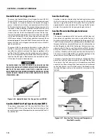
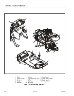
Page 46: ...SECTION 3 CHASSIS TURNTABLE 3 6 JLG Lift 3121290 Figure 3 4 Drive Hub 4WD Front Only ...
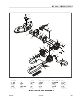
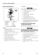
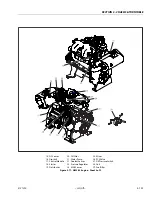
Page 79: ...SECTION 3 CHASSIS TURNTABLE 3121290 JLG Lift 3 39 Figure 3 32 Swing Bearing Drive ...
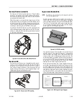
Page 101: ...SECTION 3 CHASSIS TURNTABLE 3121290 JLG Lift 3 61 Figure 3 42 Auxiliary Pump ...
Page 113: ...SECTION 3 CHASSIS TURNTABLE 3121290 JLG Lift 3 73 Figure 3 53 EMR2 Fault Codes Sheet 1 of 5 ...
Page 114: ...SECTION 3 CHASSIS TURNTABLE 3 74 JLG Lift 3121290 Figure 3 54 EMR2 Fault Codes Sheet 2 of 5 ...
Page 115: ...SECTION 3 CHASSIS TURNTABLE 3121290 JLG Lift 3 75 Figure 3 55 EMR2 Fault Codes Sheet 3 of 5 ...
Page 116: ...SECTION 3 CHASSIS TURNTABLE 3 76 JLG Lift 3121290 Figure 3 56 EMR2 Fault Codes Sheet 4 of 5 ...
Page 117: ...SECTION 3 CHASSIS TURNTABLE 3121290 JLG Lift 3 77 Figure 3 57 EMR2 Fault Codes Sheet 5 of 5 ...
Page 159: ...SECTION 3 CHASSIS TURNTABLE 3121290 JLG Lift 3 119 ...
Page 161: ...SECTION 3 CHASSIS TURNTABLE 3121290 JLG Lift 3 121 ...
Page 163: ...SECTION 3 CHASSIS TURNTABLE 3121290 JLG Lift 3 123 ...
Page 165: ...SECTION 3 CHASSIS TURNTABLE 3121290 JLG Lift 3 125 ...
Page 173: ...SECTION 3 CHASSIS TURNTABLE 3121290 JLG Lift 3 133 Sensor Transducer Type ...
Page 177: ...SECTION 3 CHASSIS TURNTABLE 3121290 JLG Lift 3 137 Sensor Transducer Type ...
Page 179: ...SECTION 3 CHASSIS TURNTABLE 3121290 JLG Lift 3 139 ...
Page 181: ...SECTION 3 CHASSIS TURNTABLE 3121290 JLG Lift 3 141 ...
Page 183: ...SECTION 3 CHASSIS TURNTABLE 3121290 JLG Lift 3 143 ...
Page 185: ...SECTION 3 CHASSIS TURNTABLE 3121290 JLG Lift 3 145 ...
Page 187: ...SECTION 3 CHASSIS TURNTABLE 3121290 JLG Lift 3 147 ...
Page 203: ...SECTION 3 CHASSIS TURNTABLE 3121290 JLG Lift 3 163 ...
Page 207: ...SECTION 3 CHASSIS TURNTABLE 3121290 JLG Lift 3 167 ...
Page 217: ...SECTION 4 BOOM PLATFORM 3121290 JLG Lift 4 5 Figure 4 2 Boom Limit Switches ...
Page 310: ...SECTION 5 HYDRAULICS 5 70 JLG Lift 3121290 NOTES ...
Page 312: ...SECTION 6 JLG CONTROL SYSTEM 6 2 JLG Lift 3121290 Figure 6 2 Controller Block Diagram 0 ...
Page 370: ...SECTION 6 JLG CONTROL SYSTEM 6 60 JLG Lift 3121290 NOTES ...
Page 394: ...SECTION 7 BASIC ELECTRICAL INFORMATION SCHEMATICS 7 24 JLG Lift 3121290 NOTES ...
Page 395: ......


