


JetMove 105
5.1 Electrical Specification
Jetter AG
35
5
Technical Specifications
5.1
Electrical Specification
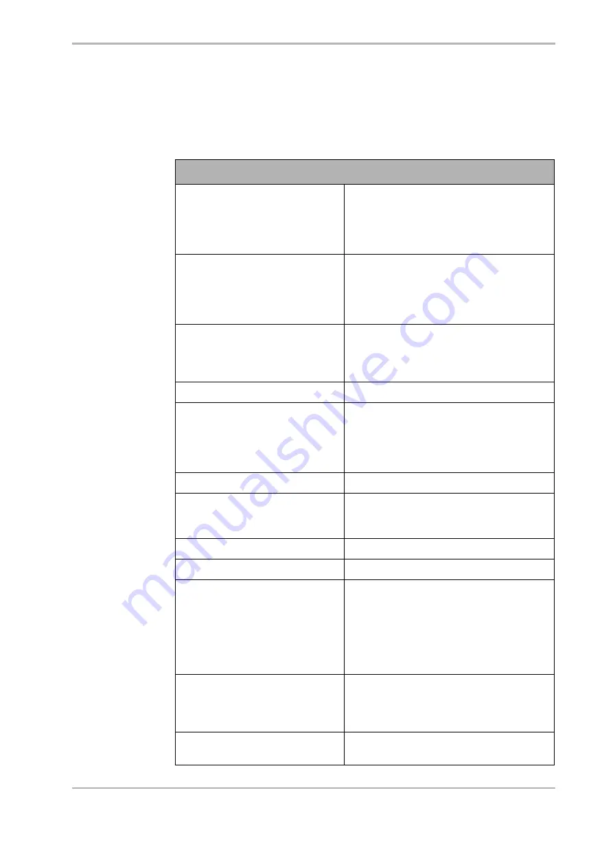
Electrical Specification
Rated voltage supply
• 24 / 48 V DC (12 ... 48 V DC)
I
max.
=
27.5 A
• The voltage output has to comply with
the power supply unit of the SELV or
PELV type.
Inrush current limitation
The JM-105 is equipped with an internal
200 µF capacitors for buffering.
The inrush current is not limited.
See "Recommendations on the power
supply circuit bVmot" on page 44.
Supply cable
Cable size
Material
Temperature class
1.0 mm
2
min.
Copper
> 60 °C
Max. output voltage of the motor
60 V
Motor output current at an ambient
temperature of 40 °C
Nominal current: I
eff
= 8 A
Peak current: I
eff
= 16 A (t <= 10 s at
T < 40°C)
Continuous output
384 W
Short-circuit protection, motor side
Designed for
• phase to phase
• phase to 0 V or ground
Motor overload protection
See "Motor Protection" on page 38.
Motor inductivity
125 µH min. between any two motor lines
Motor cable
Cable size
Material
Capacity
Temperature class
Maximum length
4 * 0.75 mm
2
min. (AWG 18)
Copper
< 150 pF/m
> 60 °C
maximum line length is 25 m
(for greater length please contact Jetter AG)
Ballast resistor
An internal ballast resistor has not been
installed. If the DC link voltage increases too
much at decelerating the motor, install an
external ballast resistor.
Residual voltage
The DC link voltage is discharged within 10
seconds at switching off the device.
Summary of Contents for JM-105
Page 1: ...User Manual JM 105 Digital Servo Amplifier 60872838 We automate your success...
Page 10: ...Table of Contents JetWeb 10 Jetter AG...
Page 21: ...JetMove 105 2 2 Mechanical Installation Jetter AG 21 Fig 3 Recommended mounting m i n 2 5 m m...
Page 26: ...2 Installing the JetMove 105 26 Jetter AG...
Page 32: ...3 Operating Conditions 32 Jetter AG...
Page 34: ...4 Physical Dimensions 34 Jetter AG...
Page 40: ...5 Technical Specifications 40 Jetter AG...
Page 84: ...7 Description of Connections 84 Jetter AG...
Page 96: ...11 Ordering Information 96 Jetter AG...
Page 97: ...JetMove 105 Appendices Jetter AG 97 Appendices...
Page 98: ...Appendices 98 Jetter AG...