background image

Center Planetary Gear Set

The annulus gear (10) is driven at the same speed

as the rear planetary carrier (15) as a result of a
mechanical connection. The sun gear (22) is held
against the housing by the multiple-disc holding
clutch B2 (6). The planetary pinion gears (18) turn
on the fixed sun gear (22) and increase the torque
from the annulus gear (10) to the planetary carrier
(14). The output shaft (5) connected to the planetary
carrier (14) turns at a reduced speed in the running
direction of the engine.

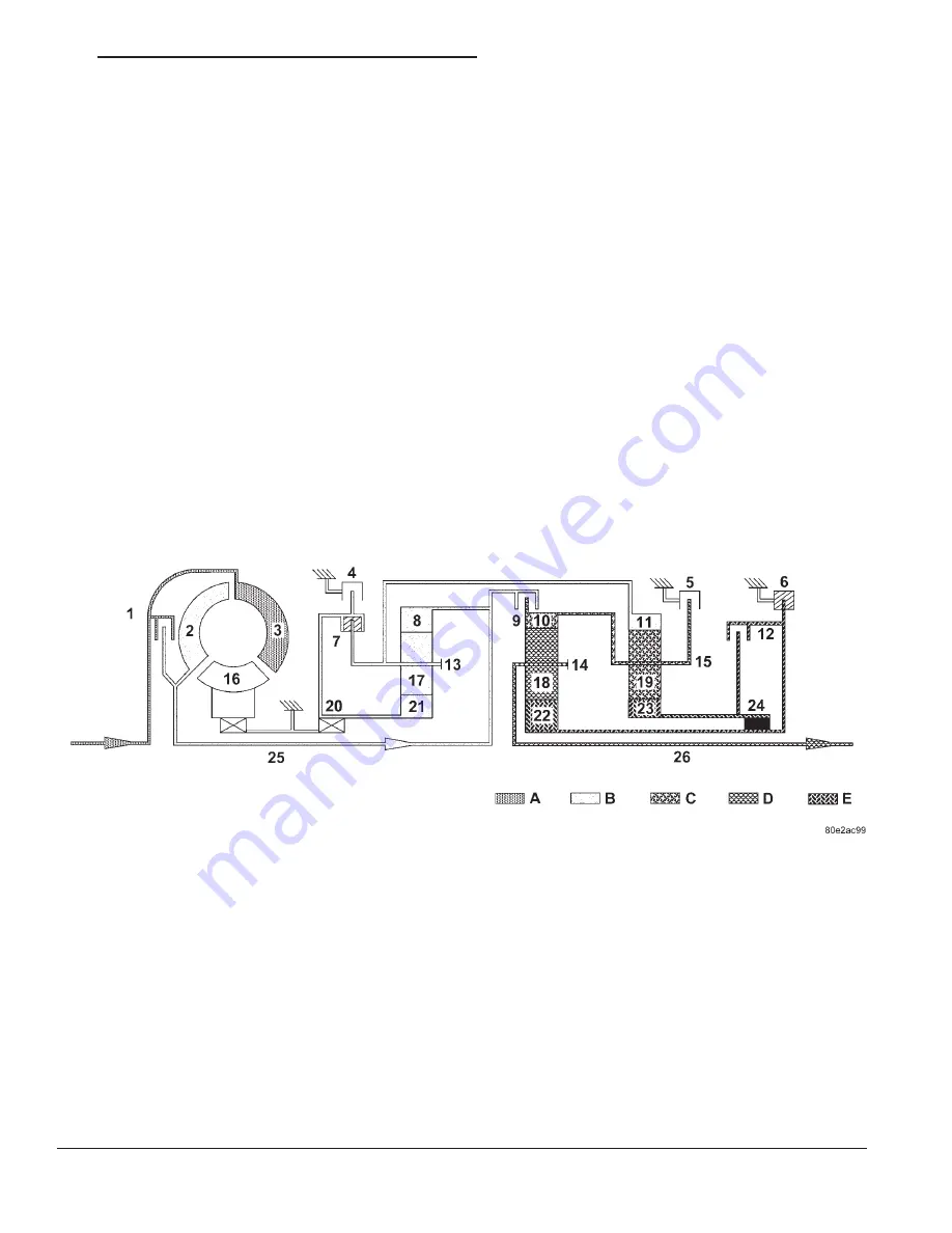
Fig. 4 Second Gear Powerflow

1 - TORQUE CONVERTER LOCK-UP CLUTCH

14 - CENTER PLANETARY CARRIER

2 - TORQUE CONVERTER TURBINE

15 - REAR PLANETARY CARRIER

3 - TORQUE CONVERTER IMPELLER

16 - TORQUE CONVERTER STATOR

4 - HOLDING CLUTCH B1

17 - FRONT PLANETARY PINION GEARS

5 - HOLDING CLUTCH B3

18 - CENTER PLANETARY PINION GEARS

6 - HOLDING CLUTCH B2

19 - REAR PLANETARY PINION GEARS

7 - DRIVING CLUTCH K1

20 - FREEWHEELING CLUTCH F1

8 - FRONT PLANETARY ANNULUS GEAR

21 - FRONT PLANETARY SUN GEAR

9 - DRIVING CLUTCH K2

22 - CENTER PLANETARY SUN GEAR

10 - CENTER PLANETARY ANNULUS GEAR

23 - REAR PLANETARY SUN GEAR

11 - REAR PLANETARY ANNULUS GEAR

24 - FREEWHEELING CLUTCH F2

12 - DRIVING CLUTCH K3

25 - DRIVE SHAFT

13 - FRONT PLANETARY CARRIER

26 - OUTPUT SHAFT

A - ENGINE SPEED

D - SECOND GEAR RATIO

B - TRANSMISSION INPUT SPEED

E - FIXED PARTS

C - FIRST GEAR RATIO

WG

TRANSMISSION AND TRANSFER CASE

21a - 7

AUTOMATIC TRANSMISSION - W5J400 (Continued)

Summary of Contents for 2002 WJ

Page 1: ...g 8Ea Electronic Control Modules 8Fa Engine Systems 8Ia Ignition Control 9a Engine 11a Exhaust System 14a Fuel System 19a Steering 2 7L Diesel 21a Transmission and Transfer Case 25a Emissions Control 2 7L Diesel Service Manual Comment Forms Rear of Manual ...

Page 2: ...NG RECOMMENDATIONS 9 LUBRICATION MAINTENANCE SPECIFICATIONS FLUID CAPACITIES DESCRIPTION SPECIFICATION FUEL TANK 20 U S Gallons 76 Liters Engine Oil with Filter 2 7L Diesel 6 5L 6 9 qts Engine Oil with Filter 4 0L 5 7 L 6 0 qts Engine Oil with Filter 4 7L 5 7 L 6 0 qts Cooling System 2 7L Diesel 14 2L 15 qts Cooling System 4 0L 14 1 L 15 qts Cooling System 4 7L 13 7 L 14 5 qts AUTOMATIC TRANSMISSI...

Page 3: ...y Mopart brand parts lubricants and chemicals be used Mopar provides the best engineered products for servicing DaimlerChrysler Corporation vehicles FLUID TYPES DESCRIPTION DESCRIPTION ENGINE COOLANT ETHYLENE GLYCOL MIXTURES CAUTION Richer antifreeze mixtures cannot be measured with normal field equipment and can cause problems associated with 100 percent ethyl ene glycol The required ethylene gly...

Page 4: ...CE IS PERFORMED PERSONAL INJURY CAN RESULT CAUTION Use of Propylene Glycol based coolants is not recommended as they provide less freeze protection and less corrosion protection The cooling system is designed around the coolant The coolant must accept heat from engine metal in the cylinder head area near the exhaust valves and engine block Then coolant carries the heat to the radiator where the tu...

Page 5: ...IL CONTAMINANTS IN USED ENGINE OIL CAUSED BY INTERNAL COMBUSTION CAN BE HAZARDOUS TO YOUR HEALTH THOROUGHLY WASH EXPOSED SKIN WITH SOAP AND WATER DO NOT WASH SKIN WITH GASOLINE DIESEL FUEL THINNER OR SOLVENTS HEALTH PROBLEMS CAN RESULT DO NOT POLLUTE DISPOSE OF USED ENGINE OIL PROPERLY CONTACT YOUR DEALER OR GOVERN MENT AGENCY FOR LOCATION OF COLLECTION CENTER IN YOUR AREA API SERVICE GRADE CERTIF...

Page 6: ...notations are located on the label of engine oil plastic bottles and the top of engine oil cans Fig 6 DESCRIPTION A multi purpose hypoid gear lubricant which con forms to MIL L 2105C and API GL 5 quality specifi cations should be used Mopar Hypoid Gear Lubricant conforms to these specifications FRONT AXLE Lubricant is SAE 75W 140 SYNTHETIC REAR AXLE Lubricant is a thermally stable SAE 80W 90 gear ...

Page 7: ...use of special dyes to aid in detecting fluid leaks Various special additives and supplements exist that claim to improve shift feel and or quality These additives and others also claim to improve converter clutch operation and inhibit overheating oxidation varnish and sludge These claims have not been sup ported to the satisfaction of DaimlerChrysler and these additives must not be used The use o...

Page 8: ...INGS IN GROUP 8A BATTERY START ING CHARGING SYSTEMS DIAGNOSTICS DO NOT JUMP START A FROZEN BATTERY PERSONAL INJURY CAN RESULT DO NOT JUMP START WHEN MAINTENANCE FREE BATTERY INDICATOR DOT IS YELLOW OR BRIGHT COLOR DO NOT JUMP START A VEHICLE WHEN THE BATTERY FLUID IS BELOW THE TOP OF LEAD PLATES DO NOT ALLOW JUMPER CABLE CLAMPS TO TOUCH EACH OTHER WHEN CONNECTED TO A BOOSTER SOURCE DO NOT USE OPEN...

Page 9: ...at and could fail 7 Allow battery in disabled vehicle to charge to at least 12 4 volts 75 charge before attempting to start engine If engine does not start within 15 sec onds stop cranking engine and allow starter to cool 15 min before cranking again DISCONNECT CABLE CLAMPS AS FOLLOWS Disconnect BLACK cable clamp from engine ground on disabled vehicle When using a Booster vehicle disconnect BLACK ...

Page 10: ...THE TRANSMISSION IS IN THE PARK POSITION AUTO MATIC TRANSMISSION OR A FORWARD DRIVE GEAR MANUAL TRANSMISSION WARNING ENSURE VEHICLE IS ON A LEVEL SUR FACE OR THE WHEELS ARE BLOCKED TO PRE VENT VEHICLE FROM ROLLING TWO WHEEL DRIVE TOWING REAR END LIFTED CAUTION Do not use steering column lock to secure steering wheel during towing operation 2WD vehicles can be towed with the front wheels on the sur...

Page 11: ...stall tow dollies under front wheels 4 Attach wheel lift device to rear wheels and raise vehicle to towing position 5 Attach safety chains Route chains so not to interfere with tail pipe when vehicle is lifted 6 Turn the ignition switch to the OFF position to unlock the steering wheel CAUTION Do not use steering column lock to secure steering wheel during towing operation 7 Secure steering wheel i...

Page 12: ...LIGHT TAIL WIND AT IDLE SLOW TRAFFIC TRAFFIC JAMS HIGH SPEED OR STEEP GRADES Driving techniques that avoid overheating are Idle with A C off when temperature gauge is at end of normal range Increasing engine speed for more air flow is rec ommended TRAILER TOWING Consult Trailer Towing section of owners manual Do not exceed limits AIR CONDITIONING ADD ON OR AFTER MARKET A maximum cooling package sh...

Page 13: ...TRUMENT CLUSTER DIAGNOSIS AND TESTING 3 Air traped in cooling 3 Drain cooling system Refer to 7 COOLING STANDARD PROCEDURE and refill Refer to 7 COOLING STANDARD PROCEDURE 4 Radiator cap faulty 4 Replace radiator cap 5 Plugged A C or radiator cooling fins 5 Clean all debre away from A C and radiator cooling fins 6 Coolant mixture incorrect 6 Drain cooling system Refer to 7 COOLING STANDARD PROCEDU...

Page 14: ...LLAPSE WHEN ENGINE IS COOLING 1 Vacuum created in cooling system on engine cool down is not being relieved through coolant reservior overflow system 1 Replace radiator cap check vent hose between radiator and reservoir bottle for blockage also check reservoir bottle vent for blockage NOISY FAN 1 Fan blade s loose damaged 1 Replace fan blade assembly 2 Thermal viscous fan drive 2 None Normal condit...

Page 15: ...n heater hoses 2 Remove hoses remove obstruction 3 Water pump damaged 3 Replace water pump HEAT ODOR 1 Damaged or missing drive line heat shields 1 Repair or replace damaged or missing heat shields 2 Thermal viscous fan drive damaged 2 Check thermal viscous fan drive Refer to 7 COOLING ENGINE FAN DRIVE VISCOUS CLUTCH DIAGNOSIS AND TESTING 7a 4 COOLING 2 7L DIESEL WG COOLING 2 7L DIESEL Continued ...

Page 16: ... belt However cracks running along a rib not across are not nor mal Any belt with cracks running along a rib must be replaced Fig 1 Also replace the belt if it has excessive wear frayed cords or severe glazing Refer to ACCESSORY DRIVE BELT DIAGNOSIS CHART for further belt diagnosis NOISE DIAGNOSIS Noises generated by the accessory drive belt are most noticeable at idle Before replacing a belt to r...

Page 17: ...ring failure seizure 3 Replace faulty component or bearing 4 Belt glazed or hardened from heat and excessive slippage 4 Replace belt LONGITUDAL BELT CRACKING 1 Belt has mistracked from pulley groove 1 Replace belt 2 Pulley groove tip has worn away rubber to tensile member 2 Replace belt 9GROOVE JUMPING9 Belt does not maintain correct position on pulley 1 Incorrect belt tension 1 Inspect Replace te...

Page 18: ...er and rubber matrix 4 Replace belt REMOVAL CAUTION Do not attempt to check belt tension with a belt tension gauge on vehicles equipped with an automatic belt tensioner NOTE The belt routing schematics are published from the latest information available at the time of publication If anything differs between these sche matics and the Belt Routing Label use the sche matics on Belt Routing Label This...

Page 19: ...pressure to the tensioner arm pressing the arm into the belt tensioning the belt If a new belt is being installed the arrow must be within approximately 3 mm 1 8 in of indexing mark Belt is considered new if it has been used 15 minutes or less If this specification cannot be met check for The wrong belt being installed incorrect length width Worn bearings on an engine accessory A C com pressor pow...

Page 20: ...entration must always be a minimum of 44 percent year round in all climates If percentage is lower than 44 percent engine parts may be eroded by cavitation and cooling system com ponents may be severely damaged by corrosion Maximum protection against freezing is provided with a 68 percent antifreeze concentration which prevents freezing down to 67 7 deg C 90 deg F A higher percentage will freeze a...

Page 21: ...PRESSURE TESTER METHOD The engine should be at normal operating temper ature Recheck the system cold if cause of coolant loss is not located during the warm engine examina tion WARNING HOT PRESSURIZED COOLANT CAN CAUSE INJURY BY SCALDING Carefully remove coolant recovery pressure con tainer cap and check coolant level Push down on cap to disengage it from stop tabs Wipe inside of con tainer and ex...

Page 22: ...sion leak If the needle on dial of pressure tester does not fluctuate race engine a few times to check for an abnormal amount of coolant or steam This would be emitting from exhaust pipe Coolant or steam from exhaust pipe may indicate a faulty cylinder head gas ket cracked engine cylinder block or cylinder head A convenient check for exhaust gas leakage into cooling system is provided by a commerc...

Page 23: ...s if removed 2 Fill system using a 50 50 mixture of ethylene glycol antifreeze and low mineral content water Fill radiator to top and add sufficient coolant to the cool ant recovery pressure container to raise level to FULL mark 3 With heater control unit in the HEAT position operate engine with container cap in place 4 After engine has reached normal operating temperature shut engine off and allo...

Page 24: ...FROM SWALLOWING COOLANT DO NOT OPEN COOLING SYSTEM UNLESS COOLANT TEMPERATURE IS BELOW 90 C OPEN CAP SLOWLY TO RELEASE PRESSURE STORE COOL ANT IN SUITABLE AND APPROPRIATELY MARKED CONTAINER WEAR PROTECTIVE GLOVES CLOTHES AND EYE WEAR 1 Disconnect negative battery cable 2 Remove engine cover Refer to 9 ENGINE REMOVAL 3 Partailly drain coolant system Refer to 7 COOLING ENGINE COOLANT STANDARD PRO CE...

Page 25: ...ion thermostat in housing and install ther mostat housing Fig 5 Tighten bolts to 9N m 80 lbs in NOTE Inspect condition of all clamps and hoses replace as necessary 3 Connect coolant hoses and vent hose Fig 5 4 Install bracket for fuel line Fig 5 5 Close coolant drain 6 Install engine cover Refer to 9 ENGINE INSTALLATION 7 Connect negative battery cable 8 Fill coolant system to proper level with ap...

Page 26: ...ry cable 9 Fill coolant system to proper level with the appropriate coolant mixture Refer to 7 COOLING ENGINE COOLANT STANDARD PROCEDURE WARNING USE EXTREME CAUTION WHEN ENGINE IS OPERATING DO NOT PUT YOUR HANDS NEAR PULLEYS BELTS OR FAN DO NOT WEAR LOOSE CLOTHES 10 Start engine and inspect for leaks RADIATOR FAN DESCRIPTION The hydraulic fan Fig 7 replaces both the electric fan and the engine dri...

Page 27: ...ce the temperature or pressure is reduced to within operating parame ters the fan will adjust or hold its speed to maintain the temperature pressure requirements NOTE If the ECM is not requesting fan on opera tion the fan blade will spin between 100 and 500 RPM when the vehicle is at idle This is due to a controlled minimum oil flow requirement through the fan drive motor ACTIVATING THE HYDRAULIC ...

Page 28: ...hydraulic fan drive Fig 9 Remove and discard o rings from line fittings 4 Disconnect low pressure return hose at hydrau lic fan drive Fig 9 NOTE The lower mounting bolts can only be accessed from under vehicle 5 Remove two lower mounting bolts from the shroud Fig 11 6 Lower vehicle 7 Disconnect the electrical connector for the fan control solenoid 8 Disconnect the radiator upper hose at the radi a...

Page 29: ...removed from the hydraulic fan drive the o rings located on the fittings must be replaced 7 Lubricate the o rings on the fittings with power steering fluid then connect inlet and outlet high pres sure lines to fan drive Fig 12 Tighten inlet line to 49 N m 36 ft lbs tighten outlet line to 29 N m 21 5 ft lbs 8 Connect low pressure return hose to fan drive Fig 12 9 Lower vehicle Fig 9 HYDRAULIC LINES...

Page 30: ...ithin a range of 124 to 145 kPa 18 to 21 psi The pres sure relief point in pounds is engraved on top of the cap The cooling system will operate at pressures slightly above atmospheric pressure This results in a higher coolant boiling point allowing increased radi ator cooling capacity The cap contains a spring loaded pressure relief valve This valve opens when system pressure reaches the release r...

Page 31: ...ent CLEANING Clean the radiator pressure cap using a mild soap and water only INSPECTION Visually inspect the pressure valve gasket on the cap Replace cap if the gasket is swollen torn or worn Inspect the area around radiator filler neck for white deposits that indicate a leaking cap RADIATOR DESCRIPTION The radiator used with the 2 7L diesel is con structed of a horizontal down flow aluminum core...

Page 32: ...aced 3 Disconnect both pressure lines at hydraulic fan drive Refer to 7 COOLING ENGINE RADIATOR FAN REMOVAL 4 Disconnect low pressure return hose at hydrau lic fan drive Refer to 7 COOLING ENGINE RADIA TOR FAN REMOVAL 5 Disconnect fan electrical connector and set aside 6 Remove lower upper radiator and coolant pressure container hoses from radiator NOTE The lower portion of the radiator is equippe...

Page 33: ...ommets in the lower cross member and secure coolant module 3 Connect upper lower radiator and coolant pres sure container hoses then secure 4 Connect coolant fan electrical connector and assure good ECM ground to fan assembly NOTE When ever the pressure line fittings are installed at the hydraulic fan drive the O rings must be replaced 5 Connect low pressure return hose at hydraulic fan 6 Connect ...

Page 34: ...met The ECM compares input signal voltages from each input device with specifications the estab lished high and low limits of the input range that are programmed into it for that device If the input voltage is not within the specifications and other trouble code criteria are met a DTC will be stored in the ECM memory ECM OPERATING MODES As input signals to the ECM change the ECM adjusts its respon...

Page 35: ... faults for multiple components i e ECT VSS IAT sensors identify and check the shared circuits for possible problems before continu ing i e sensor grounds or 5 volt supply circuits Refer to the appropriate schematic to identify shared circuits Refer to the appropriate Diesel Powertrain Diagnostic Manual for more information INTERMITTENT CODE A DTC that is not current every time the ECM SKIM checks...

Page 36: ...ure to enter the correct country code If the incorrect country code is programmed into SKIM the SKIM must be replaced 6 Select YES to update VIN the SKIM will learn the VIN from the PCM 7 Press ENTER to transfer the secret key the PCM will send the secret key to the SKIM 8 Program ignition keys to SKIM NOTE If the ECM and the SKIM are replaced at the same time all vehicle keys will need to be repl...

Page 37: ... consistent shift quality The control system ensures that clutch operation during up shifting and downshifting is more responsive without increased harshness The TCM activates the solenoid valves and moves valves in the valve body to achieve the necessary gear changes The required pressure level is calculated from the load condition engine speed Vehicle speed from ABS module and transmission oil t...

Page 38: ...ll not recover and the DTC must be cleared from the TCM with the DRBIIIt scan tool TCM SIGNALS The TCM registers one part of the input signals by direct inputs the other part by CAN C bus In addi tion to the direct control of the actuators the TCM sends various output signals by CAN C bus to other control modules Selector Lever Position A series of 12 Hall effect switches in the SLSA inform the TC...

Page 39: ...id deactivates The TCM monitors this for the SLSA because the SLSA does not commu nicate on the CAN C bus SHIFT SCHEDULES The basic shift schedule includes up and down shifts for all five gears The TCM adapts the shift program according to driving style accelerator pedal position and deviation of vehicle speed Influencing factors are Road Conditions Incline Decline and Altitude Trailer Operation L...

Page 40: ...l as how quickly the valve can move has an effect on the pres sure The return spring for the shift member pro vides a resistance that must be overcome by the pressure in order for shift member to apply These return springs have slightly different values This also affects the application pressure and is compen sated for by fill pressure adaptation Fill Time Adaptation Engagement Time Adaptation Fil...

Page 41: ...on operation The quick learn procedure should be performed if any of the fol lowing procedures are performed Transmission Assembly Replacement Transmission Control Module Replacement Solenoid Pack Replacement Clutch Plate and or Seal Replacement Valve Body Replacement or Recondition To perform the Quick Learn Procedure the follow ing conditions must be met The brakes must be applied The engine spe...

Page 42: ...n Battery Refer to Group 8A Battery for informa tion Wiring harness and connections Refer to Group 8W Wiring for information The charging system is turned on and off with the ignition switch The generator is driven by the engine through a serpentine belt and pulley arrange ment All vehicles are equipped with On Board Diagnos tics OBD Each monitored circuit is assigned a Diagnostic Trouble Code DTC...

Page 43: ...aged internal fins REMOVAL WARNING DISCONNECT NEGATIVE BATTERY CABLE BEFORE REMOVING GENERATOR B OUT PUT WIRE FROM GENERATOR FAILURE TO DO SO CAN RESULT IN PERSONAL INJURY OR DAMAGE TO VEHICLE ELECTRICAL SYSTEM 1 Disconnect negative battery cable 2 Remove accessory drive belt from generator pulley by relieving tension on belt tensioner Refer to Cooling System for procedure 3 Remove turbo intercool...

Page 44: ...GENERATOR DECOUPLER PULLEY DESCRIPTION The generator decoupler is used only with certain engines The decoupler is used in place of the standard generator drive pulley Fig 5 OPERATION The generator decoupler is used only with certain engines The decoupler Fig 5 is a one way clutch designed to help reduce belt tension fluc tuation vibration reduce fatigue loads improve belt life reduce hubloads on c...

Page 45: ...generator and accessory drive belt Refer to Generator Removal 3 Position Special Tool 8823 VM 1048 into decoupler Fig 8 4 Determine if end of generator shaft is hex shaped Fig 9 or is splined Fig 10 If hex is used insert a 10MM deep socket into tool 8823 VM 1048 Fig 11 If splined insert a 5 16 6 point hex driver or a 10MM 12 point triple square driver into tool 8823 VM 1048 Fig 12 5 The generator ...

Page 46: ...L 8823 VM 1048 Fig 9 END OF GENERATOR SHAFT HEX 1 GENERATOR SHAFT 2 HEX Fig 10 END OF GENERATOR SHAFT SPLINED 1 GENERATOR SHAFT 2 SPLINES Fig 11 DECOUPLER REMOVAL INA HEX 1 DEEP 10 MM SOCKET 2 TOOL 8823 VM 1048 WG CHARGING 8Fa 5 GENERATOR DECOUPLER PULLEY Continued ...

Page 47: ...m generator INSTALLATION INA Decoupler 1 Thread decoupler pulley onto generator shaft by hand right hand threads 2 Position Special Tool 8823 VM 1048 into decoupler Fig 8 3 Determine if end of generator shaft is hex shaped Fig 9 or is splined Fig 10 If hex is used insert a 10MM deep socket into tool 8823 VM 1048 Fig 15 If splined insert a 5 16 6 point hex driver or a 10MM 12 point triple square dr...

Page 48: ...cial Tool 8433 Fig 13 into decou pler Align tool to hex end of generator shaft 3 Do not use an adjustable ratcheting click type torque wrench Most click type wrenches will only allow torque to be applied in a clockwise rotation Use a dial type or beam type wrench Tighten in counter clockwise rotation Fig 17 Refer to torque specifications 4 Install accessory drive belt and generator Refer to Genera...

Page 49: ...Kilowatt Voltage 12 Volts Number of Fields 4 Number of Poles 4 Number of Brushes 4 Drive Type Planetary Gear Reduction Free Running Test Voltage 11 5 Volts Free Running Test Maximum Amperage Draw 160 Amperes Free Running Test Minimum Speed 5500 rpm Solenoid Closing Maximum Voltage 7 8 Volts Cranking Amperage Draw test 350 Amperes Test at operating temperature Cold engine tight new engine or heavy ...

Page 50: ...noid wire at starter slide red colored tab to unlock push down on black colored tab while pulling connector from solenoid 7 Remove starter from vehicle INSTALLATION 2 7L DIESEL 1 Position starter motor to transmission 2 Install and tighten 2 mounting bolts Refer to torque specifications 3 Connect solenoid wire to starter solenoid Slide red colored tab to lock connector 4 Install battery cable and ...

Page 51: ......

Page 52: ...ding increases its resistance as the temperature rises and limits the current to approximately 15 25 ampere The glow plug is protected this way from overloads REMOVAL CAUTION Engine temperature must be at least 90 C 194 F before removing glow plugs If cylinder head is already removed warm cylinder head to 90 C 194 F before removing glow plugs 1 Disconnect negative battery cable 2 Remove engine cov...

Page 53: ...is started Whenever the glow plug relays are activated it will control the 12 volt 100 amp circuit for the operation of the four glow plugs Each relay control two glow plugs The Glow Plug lamp is tied to this circuit Lamp operation is also controlled by the ECM With a cold engine the glow plug relays and glow plugs may be activated for a maximum time of 200 seconds Refer to the following Glow Plug...

Page 54: ...REMOVAL VALVE SPRINGS 21 REMOVAL VALVES 21 INSTALLATION INSTALLATION VALVE SPRINGS 22 INSTALLATION VALVES 22 CAMSHAFT S STANDARD PROCEDURE CHECKING CAMSHAFT POSITION 23 REMOVAL 24 INSTALLATION 25 ENGINE BLOCK STANDARD PROCEDURE STANDARD PROCEDURE REPLACING ENGINE CORE AND OIL GALLERY PLUGS 26 STANDARD PROCEDURE MEASURING CYLINDER BORES 27 CRANKSHAFT STANDARD PROCEDURE MEASURE CRANKSHAFT AND BLOCK ...

Page 55: ...IL 53 ADJUSTMENTS INSTALLATION TIMING CHAIN 53 TIMING CHAIN TENSIONER REMOVAL 57 INSTALLATION 57 ENGINE 2 7L DIESEL DESCRIPTION DESCRIPTION This 2 7 Liter five cylinder Common Rail Diesel Injection CDI engine is an in line overhead valve diesel engine This engine utilizes a cast iron cylin der block and an aluminum cylinder head The engine is turbocharged and intercooled This engine also has for v...

Page 56: ...ING NOTE If crankshaft rotates install retaining lock for crankshaft ring gear 1 Pressurize cylinder with compressed air and read off pressure loss at cylinder leak tester If exces sive pressure loss exists determine cause Refer to DETERMINING PRESSURE LOSS OF CYLIN DERS NOTE If the retaining lock is installed remove it rotate engine and install lock once again 2 Carry out test of other cylinders ...

Page 57: ...e 16 Disconnect both power steering cooler hoses at cooler 17 Remove power steering resivior retaining bolts 18 Lift coolant module from vehicle Refer to 7 COOLING ENGINE RADIATOR REMOVAL 19 Remove air cleaner housing assembly 20 Remove air tube at turbocharger 21 Remove air conditioning lines from compres sor 22 Remove junction block bracket from compres sor 23 Remove turbocharger outlet to charg...

Page 58: ... Install and tighten transfer case bolts 9 Install starter Refer to 8 ELECTRICAL STARTING STARTER MOTOR INSTALLATION 10 Connect transmission and transfer case elec trical connectors 11 Install and tighten torque converter bolts 12 Lower vehicle 13 Connect heater hoses 14 Connect exhaust flange retainer at turbo charger 15 Install connector bracket to left sill plate 16 Connect engine wiring harnes...

Page 59: ...stall front grill and fascia assembly 41 Fill coolant system with proper mixture to proper level Refer to 7 COOLING ENGINE COOL ANT STANDARD PROCEDURE 42 Fill engine oil to proper level Refer to owners manual for specifications 43 Connect negative battery cable 44 Evacuate and recharge air conditioning Refer to 24 HEATING AIR CONDITIONING PLUMB ING STANDARD PROCEDURE Refer to 24 HEATING AIR CONDIT...

Page 60: ...t Oil Pan to Timing Case Cover 9 80 Bolt Oil Pan to Transmission Bell Housing 40 30 Plug Pil Pan to Oil Drain 47 35 Connecting Rod Bolt Connecting Rod Cap to Connecting Rod 3 stage 1 2 torque 3 torque angle 5 25 90 44 221 Crankshaft Bolt Crankshaft Bearing Cap 2 stage 1 torque 2 torque angle 55 90 40 5 Flywheel Driven Plate Vibration Damper Starter Ring Gear 8 8m Bolt Central Bolt of Vibration Dam...

Page 61: ...o Timing Case Cover 30 22 Exhaust Manifold Nut Exhaust Manifold at Cylinder Head 30 22 Position Sensor Nut Bolt Camshaft Position Sensor to Cylinder Head Cover 11 97 Nut Bolt Crankshaft Position Sensor to Engine Block 8 70 Pre Glow System Cylinder Head to Glow Plug 12 106 Starter Bolt Starter to Crankcase 42 31 Nut Connection of Circuit 30 14 124 Nut Connection of Circuit 50 6 53 Alternator Bolt G...

Page 62: ...ut Rear Engine Mount to Transmission 40 26 Bolt Shrowd to Engine Bracket 10 88 5 Nut Front Engine Mount to Engine Bracket 65 48 Nut Engine Mount to Vehicle Frame 35 26 Fuel Filter Bolt Clip to Fuel Filter 8 70 Bolt Fuel Filter to Charge Air Distribution Pipe 14 124 Exhaust System Bolt Catalytic Converter Bracket to Crankcase 20 177 Clamp Connection Between Front Exhaust Pipe and Rear Exhaust Syste...

Page 63: ...5 26 44 Bolt Rail to Cylinder Head 14 124 Bolt Shutoff Valve to Cylinder Head 8 70 Nut Pressure Line to Rail Injector New Reused 22 25 16 18 5 Nut Pressure Line to High Pressure Pump Rail 22 16 Screw Tensioning Claw to Injector 2 stage 1 torque 2 torque angle 7 90 62 Rail Pressure Sensor to Rail 22 16 Pressure Pipe Connection to Injector 42 31 Threaded Rail to Rail 22 16 Fuel Cooling System Bolt F...

Page 64: ...SPECIAL TOOLS 8927 COMPRESSION TESTER ADAPTER 8928 FUEL PRESSURE TESTER 8929 CAMSHAFT LOCKING PIN 8931 TIMING CHAIN RETAINER WG ENGINE 9a 11 ENGINE 2 7L DIESEL Continued ...

Page 65: ... 8932 CRANKSHAFT LOCK 8936 FRONT CRANKSHAFT SEAL INSTALLER 8937 SLIDE HAMMER 8938 INJECTOR REMOVER 9a 12 ENGINE WG ENGINE 2 7L DIESEL Continued ...

Page 66: ... 8940 VIBRATION DAMPER REMOVER 8942 OIL JET INSTALLER 8944 REAR MAIN SEAL INSTALLER 8945 ADAPTER CABLE WG ENGINE 9a 13 ENGINE 2 7L DIESEL Continued ...

Page 67: ... 8946 VALVE SERVICE TOOLS 8947 RIVET OPENER 8948 CHAIN SEPARATOR TOOL 8949 THRUST PIECE 9a 14 ENGINE WG ENGINE 2 7L DIESEL Continued ...

Page 68: ... 8950 PRESSING SCREW 8951 ASSEMBLY LINKS 8952 ASSEMBLY INSERTS WG ENGINE 9a 15 ENGINE 2 7L DIESEL Continued ...

Page 69: ...ylinder head and cylinder block flatness 6 Measure cylinder head height at point 1 indi cated and retain reading Fig 6 NOTE The camshaft housing Must Not be machined Basic bore of the camshaft bearings will be altered 7 Machine cylinder head contact surface if nec essary 8 Measure cylinder head height 1 at point indi cated record stock removal Fig 6 CYLINDER HEAD SPECIFICATIONS 9 Measure valve set...

Page 70: ...17 Remove timing chain tensioner Refer to 9 ENGINE VALVE TIMING TIMING BELT CHAIN AND SPROCKETS REMOVAL 18 Remove cylinder head front cover Refer to 9 ENGINE CYLINDER HEAD REMOVAL 19 Remove top guide rail Refer to 9 ENGINE VALVE TIMING TIMING BELT CHAIN AND SPROCKETS REMOVAL 20 Remove camshafts Refer to 9 ENGINE CYL INDER HEAD CAMSHAFT S REMOVAL 21 Remove idler gear Refer to 9 ENGINE VALVE TIMING ...

Page 71: ... ENGINE ENGINE BLOCK INTERNAL VACUUM PUMP REMOVAL 10 Remove bolts attaching front cover NOTE Lower portion of front cover is sealed with RTV sealant Carefully tug at front cover until it loosens from cylinder head 11 Raise locking pawl of top guide rail and remove cylinder head front cover Fig 7 NOTE Dowel pins are use as a guide during assembly and must remain in the proper position to assure a g...

Page 72: ...stall M12 cylinder head bolts finger tight 2 Torque bolts in numeric order starting with number 1 to 60 N m 44 lbs in Fig 8 3 Install M8 timing chain cover to cylinder head bolts 1A Fig 8 Tighten to 20N m 177 lbs in 4 Tighten M12 cylinder head bolts in numeric order starting with number 1 an additional 90 Fig 8 5 Tighten M12 cylinder head bolts in numeric order starting with number 1 an additional...

Page 73: ...onto guide pins 3 Install bolts attaching front cover Fig 7 Tighten bolts to 14N m 124 lbs in WARNING NO FIRE OPEN FLAMES OR SMOKING REMOVE SOURCES OF IGNITION FROM THE AREA WEAR PROTECTIVE CLOTHING WHEN HANDLING FUEL RISK OF POISONING FROM INHALING AND SWALLOWING FUEL RISK OF INJURY FROM SKIN AND EYE CONTACT WITH FUEL POUR FUELS ONLY INTO SUITABLE AND APPROPRIATELY MARKED CONTAINERS 4 Instal low ...

Page 74: ...COVER S REMOVAL 5 Remove timing chain tensioner Refer to 9 ENGINE VALVE TIMING TIMING BELT CHAIN AND SPROCKETS REMOVAL 6 Remove front cover at cylinder head Refer to 9 ENGINE CYLINDER HEAD REMOVAL 7 Remove top guide rail Refer to 9 ENGINE CYLINDER HEAD REMOVAL 8 Remove camshafts Refer to 9 ENGINE CYL INDER HEAD CAMSHAFT S REMOVAL NOTE The timing chain must be held in up position so as not to jam d...

Page 75: ...oling from cylinder head 10 Position piston of 1 cylinder to ignition TDC 11 Install camshafts and check basic position Refer to 9 ENGINE CYLINDER HEAD CAM SHAFT S INSTALLATION 12 Install top guide rail Refer to 9 ENGINE CYLINDER HEAD INSTALLATION 13 Install front cover at cylinder head Refer to 9 ENGINE CYLINDER HEAD INSTALLATION 14 Install timing chain tensioner with new gas ket Refer to 9 ENGIN...

Page 76: ... FROM CONTACT WITH FUEL POUR FUEL ONLY INTO SUITABLE AND MARKED CON TAINERS WEAR PROTECTIVE CLOTHING WHEN HANDLING FUEL 1 Remove injectors Refer to 14 FUEL SYS TEM FUEL INJECTION FUEL INJECTOR REMOVAL 2 Clean injectors and recesses Refer to 14 FUEL SYSTEM FUEL INJECTION FUEL INJEC TOR STANDARD PROCEDURE 3 Remove cylinder head cover Refer to 9 ENGINE CYLINDER HEAD CYLINDER HEAD COVER S REMOVAL NOTE...

Page 77: ...FUEL INJECTOR REMOVAL 4 Remove cylinder head cover Refer to 9 ENGINE CYLINDER HEAD CYLINDER HEAD COVER S REMOVAL 5 Position piston of cylinder 1 to ignition TDC 6 Lock inlet camshaft Fig 10 7 Remove timing chain tensioner Refer to 9 ENGINE VALVE TIMING TIMING BELT CHAIN AND SPROCKETS REMOVAL NOTE The lower portain of the cylinder head front cover is sealed with RTV sealant Carefully tug front cove...

Page 78: ...GINE CYLINDER HEAD CAMSHAFT S STANDARD PROCEDURE 3 Position piston of cylinder 1 to 30 TDC NOTE Pay attention to markings on camshaft bear ing caps 4 Install camshaft bearing caps in the proper order Tighten bolts to 9N m 80 lbs in CAUTION Do not rotate engine counter clockwise 5 Position the piston of cylinder 1 to ignition TDC NOTE Pay attention to markings on camshaft bear ing caps 6 Install th...

Page 79: ...ANDARD PROCEDURE REPLACING ENGINE CORE AND OIL GALLERY PLUGS Using a blunt tool such as a drift and a hammer strike the bottom edge of the cup plug With the cup plug rotated grasp firmly with pliers or other suit able tool and remove plug Fig 12 CAUTION Do not drive cup plug into the casting as restricted cooling can result and cause serious engine problems Thoroughly clean inside of cup plug hole...

Page 80: ...r bores Standard size 88 0 mm Group code letter A 88 000 88 006 mm Group code letter X 88 006 88 012 mm Group code letter B 88 012 88 018 mm Wear limit in longitudinal in transverse direction 0 020 mm Permissible variation of cylinder shape when new 0 000 0 014 mm Fig 13 MEASURING CYLINDER BORES 1 MEASURING POINT OF CYLINDER BORE 2 MEASURING POINT OF CYLINDER BORE 3 MEASURING POINT OF CYLINDER BOR...

Page 81: ...ls ASSIGN CRANKSHAFT BEARING SHELLS The oil pan rail of the cylinder block is marked with chisel punches indicating what bearing shell are used 9 Assign crankshaft bearing shells 10 Mount crankshaft axially 11 Inspect crankshaft bearing play REMOVAL 1 Remove engine Refer to 9 ENGINE REMOVAL 2 Remove timing case cover Refer to 9 ENGINE VALVE TIMING TIMING BELT CHAIN COVER S REMOVAL 3 Remove end cov...

Page 82: ... engine and inspect for leaks CRANKSHAFT OIL SEAL REAR REMOVAL This must be done with the transmission removed from the vehicle 1 Disconnect the negative battery cable 2 Raise and support the vehicle 3 Drain the engine oil NOTE Loosen all of the oil pan bolts to assure that the oil pan gasket is not damaged when removing the rear main oil seal and end cover assembly NOTE Inspect the oil pan gasket...

Page 83: ...e a puller to remove it Do Not tilt the puller The groves of the puller MUST mesh fully into the slots of the belt pulley NOTE Inspect the running surface of the belt pulley for wear 4 Remove the belt pully vibration damper CAUTION Care must be taken to prevent severe damage to the crankshaft and mounting whole for the front crankshaft seal 5 Using a suitable prying tool remove the front crankshaf...

Page 84: ...E IS OPERATING DO NOT STAND IN A DIRECT LINE WITH THE FAN DO NOT PUT YOUR HANDS NEAR THE PULLEYS BELTS OR FAN DO NOT WEAR LOOSE CLOTHES 7 Start the engine and inspect for leaks FLYWHEEL REMOVAL 1 Remove transmission Refer to 21 TRANS MISSION TRANSAXLE AUTOMATIC W5J400 REMOVAL NOTE M6x90 bolts must be used with retaining lock to prevent damage to rear end cover 2 Install retaining lock for cranksha...

Page 85: ...ock lubricate and cool the piston and pin assembly The connecting rods have a pressed in place wrist pin bushing which is lubricated by the oil jets Fig 18 STANDARD PROCEDURE STANDARD PROCEDURE CHECKING AND REPAIRING CONNECTING RODS NOTE Connecting rods with blue discoloration cross scores or notches must be replaced Com pensate for different weights by milling off the bal ancing weight 1 Inspect ...

Page 86: ...re at connecting rod bushing bore 21 940 mm to 22 mm Connecting rod bearing shell basic bore 51 600 mm to 51 614 mm Allowable out of roundness and taper of basic bore 020 mm Allowable twist of connecting rod bearing bore to connecting rod bushing bore over a length of 100 mm 100 mm Allowable variation of axial parallelism of connecting rod bearing bore to connecting rod bushing bore over a length ...

Page 87: ...from the oil pump 6 Remove the oil pump NOTE Mark the connecting rod and connecting rod bearing cap to each other at the inlet side 7 Remove the connecting rod bearing cap NOTE Do Not mix up the top and bottom connect ing rod bearing shells 8 Mark the connecting rod bearing shell and the connecting rod bearing cap to each other NOTE If the pistons are used the direction of travel arrows and the ma...

Page 88: ...n not to damage the piston 5 Insert circle clip of piston pin into groove on piston Fig 22 6 Using the appropriate clean engine oil clean the cylinder bores connecting rod bearing journals connecting rod bearing shells and pistons CAUTION Offset the piston ring gaps by 120 7 Position a ring compressor over piston and rings Tighten ring compressor Fig 23 Ensure that ring position does not change du...

Page 89: ... con necting rod bearing cap CAUTION The markings on the connecting rod and connecting rod cap must be lined up 11 Install connecting rod bearing cap Tighten bolts in 3 stages 5N m 44 lbs in 25N m 221 lbs in 90 12 Rotate crankshaft fully and check the clear ance Fig 22 PISTON AND CONNECTING ROD ASSEMBLY 1 CIRCLE CLIP 2 PISTON PIN 3 PISTON ASSEMBLY 4 CONNECTING ROD ALIGNMENT MARKINGS 5 CONNECTING R...

Page 90: ...TING DO NOT STAND IN A DIRECT LINE WITH THE FAN DO NOT PUT YOUR HANDS NEAR THE PULLEYS BELTS OR FAN DO NOT WEAR LOOSE CLOTHES 21 Start the engine and inspect for leaks PISTON RINGS STANDARD PROCEDURE PISTON RING FITTING 1 Carefully clean the carbon from all ring grooves Oil drain openings in the oil ring groove and pin boss must be clear DO NOT remove metal from the grooves or lands This will chan...

Page 91: ...6 Using a ring expander install compression rings with manufactures designation pointing toward piston crown Fig 26 Ring Gap Orientation Position the gaps on the piston as shown Fig 27 Oil spacer Gap on center line of piston skirt Oil rails gap 180 apart on centerline of piston pin bore No 2 Compression ring Gap 120 from top oil rail gap No 1 Compression ring Gap 120 from No 2 compression ring gap...

Page 92: ...tages M8 8 bolt to 200N m 148 lbs ft then 90 M10 9 bolt to 325N m 240 lbs ft then 90 NOTE Inspect accessory drive belt for wear Replace as necessary 3 Install accessory drive belt Refer to 7 COOL ING ACCESSORY DRIVE DRIVE BELTS INSTAL LATION 4 Reconnect negative battery cable WARNING USE EXTREME CAUTION WHEN THE ENGINE IS IN OPERATION DO NOT STAND IN A DIRECT LINE WITH THE FAN DO NOT PUT YOUR HAND...

Page 93: ...all vac uum pump with new seals Tighten bolts to 14N m 124 lbs in 3 Install vacuum line to vacuum pump 4 Reconnect cooling fan power steering hose 5 Reconnect viscous heater pipe 6 Install engine cover Refer to 9 ENGINE INSTALLATION Tighten screws to 10 N m 89 lbs in 7 Connect negative battery cable 8 Refill coolant system with correct mixture to proper level Refer to 7 COOLING ENGINE COOL ANT STA...

Page 94: ...over Refer to 9 ENGINE REMOVAL NOTE Oil pan bolts are different diameters and lengths and must be installed in their proper position 5 Remove oil pan bolts oil pan and gasket INSTALLATION NOTE Thoroughly clean all mating surfaces with the appropriate solvents to assure that no grease or oil is present during reassembly NOTE Oil pan bolts are different diameters and lengths They must be installed i...

Page 95: ...nstallation pro cedure for the oil pump chain is followed exactly Failure to do so will result in severe engine dam age INSTALLATION INSTALLATION NOTE Clean strainer of oil pump If oil pump is dry fill with appropriate engine oil 1 Position oil pump and install oil pump chain 2 Install oil pump and seal Tighten bolts to 18N m 159 lbs in 3 Install oil pan Refer to 9 ENGINE LUBRI CATION OIL PAN INST...

Page 96: ... outer plate and assembly link Fig 35 CAUTION Insert new riveted link from the rear 4 Connect ends of new oil pump chain with new riveted link Fig 36 NOTE When assembling riveting tool one piece is secured by a screw and the other can move loosely on the thrust spindle Fig 34 INSTALLING OIL PUMP CHAIN TEMPORARY LINK 1 VIBRATION DAMPER CRANKSHAFT PULLEY 2 OLD OIL PUMP CHAIN 3 NEW OIL PUMP CHAIN 4 T...

Page 97: ...iveting tool so that spacer webs of the guide are side by side 13 Ensure that riveted link and outer plate are aligned NOTE When turning spindle of riveting tool be sure that pins of riveted link are inserted into holes of outer plate 14 Screw in spindle of riveting tool until firm resistance is felt 15 Remove riveting tool 16 Turn over tool moving assembly insert to the riveting profile NOTE Rive...

Page 98: ...anger to cylinder head 9 Remove air charge distribution pipe Refer to 11 EXHAUST SYSTEM TURBOCHARGER SYS TEM REMOVAL 10 Remove coolant hose at oil water heat exchanger NOTE Collect any residual fluids that may flow 11 Remove automatic transmission fluid line at oil water heat exchanger 12 Remove oil water heat exchanger at timing case cover INSTALLATION OIL COOLER 1 Install oil cooler to timing ca...

Page 99: ...e flaps are opened TIMING CHAIN COVER REMOVAL WARNING DO NOT OPEN COOLING SYSTEM UNLESS TEMPERATURE IS BELOW 90 c 194 F OPEN CAP SLOWLY TO RELEASE PRESSURE STORE COOLANT IN APPROVED CONTAINER ONLY RISK OF INJURY TO SKIN AND EYES FROM SCALDING COOLANT WEAR PROTECTIVE GLOVES CLOTHING AND EYE WEAR 1 Disconnect negative battery cable 2 Drain coolant Refer to 7 COOLING ENGINE COOLANT STANDARD PROCEDURE...

Page 100: ...ead on timing case cover 29 Remove timing case cover Fig 42 30 Remove remaining ancillary components attached to the timing case cover INSTALLATION NOTE Thoroughly clean all mating surfaces with the appropriate solvents to assure that no grease or oil is present during assembly 1 Inspect cylinder head gasket and oil pan gas ket If damaged replace 2 Replace the front crankshaft seal Refer to 9 ENGI...

Page 101: ...coolant to the proper level with the proper coolant Refer to 7 COOLING ENGINE COOLANT STANDARD PROCEDURE 28 Tighten the oil drain plug to 30N m 265 lbs in 29 Fill the crankcase with the correct oil to the proper level Refer to owners manual for specifica tions 30 Connect the negative battery cable WARNING USE EXTREME CAUTION WHEN THE ENGINE IS OPERATING DO NOT STAND IN A DIRECT LINE WITH THE FAN D...

Page 102: ...INJEC TION PUMP REMOVAL 11 Mark camshaft sprocket relative to timing chain 12 Unbolt camshaft sprocket from exhaust cam shaft NOTE Note position of dowel pin for camshaft sprocket alignment during reassembly 13 Secure camshaft sprocket to timing chain with tie strap 14 Remove camshaft sprocket 15 Remove intermediate gear and bushing Fig 44 REMOVAL TIMING CHAIN TENSIONING RAIL 1 Disconnect negative...

Page 103: ...ached from camshaft NOTE When fitting the thrust spindle ensure that the thrust pin is positioned at the left timing chain pin of a chain link Fig 47 8 Using special tool 8948 position timing chain separating tool at the timing chain of the camshaft sprocket Fig 48 9 Screw the thrust pin in and separate the tim ing chain 10 Unscrew the thrust spindle and remove the tool NOTE DO NOT detach timing c...

Page 104: ...r oil is present during reassembly 1 Install slide rail on bearing pin 2 Install timing cover Refer to 9 ENGINE VALVE TIMING TIMING BELT CHAIN COVER S INSTALLATION 3 Install oil pan bolts Tighten M6 bolts to 9N m 80 lbs in and M8 bolts to 20N m 15 lbs ft 4 Install cylinder head Refer to 9 ENGINE CYLINDER HEAD INSTALLATION 5 Reconnect negative battery cable WARNING USE EXTREME CAUTION WHEN THE ENGI...

Page 105: ...ing chain tensioner with new gasket Refer to 9 ENGINE VALVE TIMING TIMING BELT CHAIN AND SPROCKETS INSTALLATION NOTE Inspect basic position of camshaft and reset if necessary 8 Remove camshaft locking pin 9 Install cylinder head cover Refer to 9 ENGINE CYLINDER HEAD CYLINDER HEAD COVER S INSTALLATION WARNING NO FIRE FLAMES OR SMOKING SERVIVE VEHICLE IN WELL VENTILATED AREA RISK OF INJURY FROM INHA...

Page 106: ...ON WHEN THE ENGINE IS OPERATING DO NOT PUT YOUR HANDS NEAR THE PULLEYS BELTS OR FAN DO NOT WEAR LOOSE CLOTHES 6 Start the engine and inspect for leaks ADJUSTMENTS INSTALLATION TIMING CHAIN CAUTION IT IS ESSENTIAL that the installation pro cedure is followed exactly Failure to do so will result in severe engine damage CAUTION Cover timing case recesses to prevent foreign material from entering engi...

Page 107: ...h new timing chain to camshaft sprocket and retain 5 Insert new riveted link and new middle plate into ends of timing chain Fig 54 6 Take off retaining devise at cylinder head 7 Remove camshaft sprocket from camshaft with timing chain secured NOTE When assembling riveting tool piece F5 is secured by a screw and D9 can move loosely on thrust spindle 8 Assemble riveting tool by inserting pieces F5 a...

Page 108: ...t spacer webs of the guide are side by side 15 Ensure that riveted link and outer plate are aligned Fig 58 NOTE When turning spindle of riveting tool be sure that pins of riveted link are inserted into holes of outer plate Fig 58 16 Screw in spindle of riveting tool until firm resistance is felt Fig 58 Fig 56 PRESSING IN NEW RIVETED LINK 1 SPECIAL TOOL 8947 2 NEW RIVETED LINK 3 SPECIAL TOOL 8952 F...

Page 109: ...4 FUEL SYSTEM FUEL DELIVERY FUEL INJEC TION PUMP INSTALLATION 27 Install timing chain tensioner Refer to 9 ENGINE VALVE TIMING TIMING BELT CHAIN AND SPROCKETS INSTALLATION 28 Install vacuum pump Refer to 9 ENGINE ENGINE BLOCK INTERNAL VACUUM PUMP INSTALLATION 29 Install cylinder head cover Refer to 9 ENGINE CYLINDER HEAD CYLINDER HEAD COVER S INSTALLATION 30 Install engine cover Refer to 9 ENGINE ...

Page 110: ... tensioner Fig 61 INSTALLATION NOTE Carefully clean all mating surfaces with appropriate solvents to assure that no grease or oil is present during reassembly 1 Install timing chain tensioner with new gasket Tighten to 80N m 59 lbs ft 2 Install viscous heater 3 Install idler pulley and accessory drive belt Refer to 7 COOLING ACCESSORY DRIVE DRIVE BELTS INSTALLATION 4 Install intake air scoop 5 Rec...

Page 111: ......

Page 112: ... pipe if needed muffler and exhaust tailpipe The exhaust system must be properly aligned and secured to prevent stress leakage and body contact The exhaust components should be kept a minimum of 25 4 mm 1 0 in away from the body and frame If the system contacts any body panel it may amplify objectionable noises from the engine or body DIAGNOSIS AND TESTING DIESEL ENGINE EXHAUST SYSTEM DIAGNOSIS CH...

Page 113: ...e same speed The fresh air inducted by the compressor wheel is compressed and passed to the engine Fig 2 The charge pressure is controlled by varying the position of the guide vanes Fig 2 The guide stud of the control linkage of the boost pressure actuator turns the adjusting ring in the turbine housing Fig 2 As a result all the guide vanes whose guide studs likewise mesh into the adjusting ring a...

Page 114: ...arge air inlet tube to turbocharger housing support bracket 6 Connect charger air inlet tube 7 Connect MAF intake tube 8 Connect oil separator tube to MAF intake tube 9 Connect negative battery cable WASTEGATE REMOVAL WASTE GATE SOLENOID 1 Disconnect negative battery cable 2 Disconnect waste gate solenoid electrical con nector 3 Disconnect engine vacuum harness from waste gate solenoid Fig 3 4 Rem...

Page 115: ...ter check the air inlet ducts rubber sleeves charge air cooler and intake manifold for leaks REMOVAL CHARGE AIR COOLER WARNING IF THE ENGINE WAS JUST TURNED OFF THE AIR INTAKE SYSTEM TUBES MAY BE HOT NOTE Note the location of the rubber air charge cooler to A C condenser and air charger cooler to radiator air seals The seals are use to prevent overheating and improve charge air and A C effi ciency...

Page 116: ... the bolts and tighten to 2 N m 17 in lbs 2 Install cooling module Refer to 7 COOLING ENGINE RADIATOR INSTALLATION Refer to 7 COOLING ENGINE RADIATOR FAN INSTALLA TION 3 Install the transmission auxiliary cooler if equipped Refer to 7 COOLING TRANSMISSION TRANS COOLER INSTALLATION 4 Install the power steering cooler 5 Install the boost tubes to the charge air cooler With the clamps in position tig...

Page 117: ......

Page 118: ... AIR TEMPERATURE SENSOR DESCRIPTION 11 OPERATION 11 CAMSHAFT POSITION SENSOR DESCRIPTION The camshaft position sensor is mounted on the cylinder head cover Fig 1 The sensor detects the camshaft position contactlessly hall effect by means of a segment at the camshaft The electronic control module ECM detects TDC position of cylinder 1 by means of the signal supplied by the camshaft sensor Injection...

Page 119: ...oth generates a positive voltage pulse and the rear edge a negative voltage pulse The distance from the positive to the negative voltage peak equals the length of a tooth The gap created by 2 missing teeth arrow has the effect that no voltage is generated in the crankshaft position sensor This is analyzed in order to detect the TDC position of cylinder 1 FUEL PRESSURE SENSOR DESCRIPTION The rail s...

Page 120: ... AND SWALLOWING FUEL RISK OF INJURY TO EYES AND SKIN FROM CONTACT WITH FUEL POUR FUELS ONLY INTO SUITABLE AND APPROPRI ATELY MARKED CONTAINERS WEAR PROTECTIVE CLOTHING 1 Coat sealing surface of fuel rail with lubricat ing varnish and replace seal 2 Counterhold at the threaded connection of the fuel rail and install the rail pressure sensor Fig 3 Tighten to 22N m 194 lbs in 3 Connect rail sensor el...

Page 121: ...ce seat The rail s high pressure build up in the valve control chamber and the same pressure is also present in the nozzle s chamber volume The rail pressure applied at the control plunger s end face together with the force of the nozzle spring maintain the nozzle in the closed position against the opening forces applied to its pressure stage Fig 5 Injector opens start of injection The solenoid va...

Page 122: ...force together with that of the spring now exceeds the force exerted by the chamber volume and the nozzle needle closes Injection ceases as soon as the nozzle needle comes up against its bottom stop again Fig 5 STANDARD PROCEDURE CLEANING FUEL INJECTORS NOTE Before cleaning the injector recesses seal the injector holes in the injector recesses with the appropriate pin to prevent debris from fallin...

Page 123: ...UEL INJECTION FUEL INJEC TOR STANDARD PROCEDURE 2 Coat injector body with anti seize lubricant then install injectors with new seals 3 Install tensioning claws with new screws at injectors Tighten screws in two stages 7 N m 62 lbs in then 90 NOTE If locking clamp has been pulled off at injec tor the locking clamp must be replaced 4 Position fuel return line at injectors and secure locking clamps N...

Page 124: ...M INHALING AND SWALLOWING FUEL RISK OF INJURY TO EYES AND SKIN FROM CONTACT WITH FUEL POUR FUELS ONLY INTO SUITABLE AND APPROPRI ATELY MARKED CONTAINERS WEAR PROTECTIVE CLOTHING 1 Disconnect negative battery cable 2 Remove engine cover Refer to 9 ENGINE REMOVAL 3 Disconnect fuel rail pressure sensor and pres sure control valve electrical connectors Fig 7 4 CAUTION When slackening and tightening fu...

Page 125: ...DO NOT WEAR LOOSE CLOTHING 10 Start engine and inspect for leaks MANIFOLD AIR FLOW MAF SENSOR DESCRIPTION The Mass Air Flow MAF Sensor is mounted inline in the air intake between the air filter and the turbocharger Fig 8 OPERATION The ECM uses the mass air flow MAF sensor to measure air density A signal voltage is provided to the MAF sensor that contains a ceramic element As engine speed increases...

Page 126: ...he tank In a de energized state the fuel pressure solenoid is closed as the spring force presses the ball into the ball seat Fig 11 When driving the fuel pressure solenoid is constantly open Fig 11 When engine is started the fuel pressure solenoid is held closed by magnetic force Fig 11 When driving the pressure of the fluid counteracts the magnetic force of the coil and the slight spring force Fi...

Page 127: ...ith screws Tighten in two stages 3N m 26 lbs in then 5N m 44 lbs ft 2 Install fuel rail Refer to 14 FUEL SYSTEM FUEL INJECTION FUEL INJECTOR INSTALLA TION 3 Install engine cover Refer to 9 ENGINE INSTALLATION 4 Connect negative battery cable WARNING USE EXTREME CAUTION WHEN ENGINE IS OPERATING DO NOT STAND IN A DIRECT LINE WITH THE FAN DO NOT PUT YOUR HANDS NEAR PULLEYS BELTS OR FAN DO NOT WEAR LO...

Page 128: ...the DRB IIIt scan tool Refer to the Diesel Powertrain Diagnostic Manual for more information Refer to On Board Diagnostics in Emissions Con trol System for a list of Diagnostic Trouble Codes DTC s for certain fuel system components INTAKE AIR TEMPERATURE SENSOR DESCRIPTION This sensor is also used to monitor the intake air temperature Fig 14 OPERATION The intake air temperature sensor is a negativ...

Page 129: ...erate hand pump until fuel flows through line free of bubbles 7 Press locking ring at bleeder valve in direction of arrow and detach inlet connection 8 Press seal into bleeder valve until it locks 9 Install engine cover Refer to 9 ENGINE INSTALLATION FUEL FILTER WATER SEPARATOR DESCRIPTION In order to assure trouble free operation with win ter grade diesel fuel a preheater valve is located with in...

Page 130: ...0 The high pressure pump is driven at about 1 3 times the speed of the camshaft The high pressure pump is mounted to the front of the cylinder head Fig 1 DESCRIPTION LOW PRESSURE PUMP The low pressure pump Fig 2 supplies an ade quate quantity of filtered fuel in all operating condi tions from the fuel tank at an adequate pressure to the high pressure pump OPERATION OPERATION LOW PRESSURE SIDE The ...

Page 131: ...el always remains relatively cool REMOVAL REMOVAL HIGH PRESSURE PUMP WARNING NO SPARKS OPEN FLAMES OR SMOK ING RISK OF POISONING FROM INHALING AND SWALLOWING FUEL RISK OF INJURY TO EYES AND SKIN FROM CONTACT WITH FUEL POUR FUELS ONLY INTO SUITABLE AND APPROPRI ATELY MARKED CONTAINERS WEAR PROTECTIVE CLOTHING 1 Disconnect negative battery cable 2 Remove engine cover Refer to 9 ENGINE REMOVAL 3 Remo...

Page 132: ...RISK OF POISONING FROM INHALING AND SWALLOWING FUEL RISK OF INJURY TO EYES AND SKIN FROM CONTACT WITH FUEL POUR FUELS ONLY INTO SUITABLE AND APPROPRI ATELY MARKED CONTAINERS WEAR PROTECTIVE CLOTHING CAUTION Clean sealing surfaces with appropriate solvents and replace all seals NOTE Inspect then attach high pressure pump driver and intermediate piece if pump is being replaced If wear is present at ...

Page 133: ...LINE WITH THE FAN DO NOT PUT YOU HANDS NEAR PULLEYS BELTS OR FAN DO NOT WEAR LOOSE CLOTHES 11 Start engine and inspect for leaks INSTALLATION LOW PRESSURE PUMP WARNING NO SPARKS OPEN FLAMES OR SMOK ING RISK OF POISONING FROM INHALING AND SWALLOWING FUEL RISK OF INJURY TO EYES AND SKIN FROM CONTACT WITH FUEL POUR FUELS ONLY INTO SUITABLE AND APPROPRI ATELY MARKED CONTAINERS WEAR PROTECTIVE CLOTHING...

Page 134: ...s free of stress CAUTION Inspect sealing cone at lines Replace if compression points exist Ensure lines are exactly located 2 Position and install fuel lines Fig 5 Tighten to 22N m 195 lbs in using a wrench to counterhold at threaded connection 3 Tighten fuel rail to 14N m 124 lbs in 4 Install engine cover Refer to 9 ENGINE INSTALLATION 5 Connect negative battery cable WARNING USE EXTREME CAUTION ...

Page 135: ......

Page 136: ...SE RESERVOIR TO THE PUMP 5 INSTALLATION 3 89 GEAR OUTLET HOSE 5 INSTALLATION INLET COOLER HOSE 5 INSTALLATION OUTLET COOLER HOSE 5 PUMP REMOVAL 1 Open the hood and disconnect the negative bat tery cable 2 Remove the intercooler outlet hose from the vehicle 3 Remove the battery Refer to the electrical sec tion 4 Siphon and drain the fluid from the pump 5 Remove the accessory drive belt from the pow...

Page 137: ...ler outlet hose on the vehi cle 8 Connect the negative battery cable 9 Fill the power steering fluid Refer to Power Steering Pump Initial Operation in this group for the procedure RESERVOIR REMOVAL 1 Siphon and drain the fluid from the pump 2 Remove the intercooler outlet hose from the vehicle 3 Remove the front fascia Refer to the body sec tion 4 Remove the cooler hose to the reservoir 5 Remove t...

Page 138: ... support the vehicle 3 Remove the metal skid plate 4 Disconnect the high pressure hose from the hydraulic fan motor 5 Lower the vehicle 6 Disconnect the high pressure hose from the power steering pump 7 Remove the hose from the clipped position on the fan shroud 8 Remove the hose from the vehicle REMOVAL RETURN HOSE RESERVOIR TO THE HYDRAULIC FAN MODULE 1 Drain the power steering fluid from the re...

Page 139: ...Place a drain pan under the cooler 6 Disconnect the lower hose at cooler 7 Disconnect the cooler hose at the gear 8 Remove the bracket holding the cooler hoses Fig 4 9 Remove the cooler hose from the vehicle REMOVAL OUTLET COOLER HOSE 1 Disconnect negative battery cable at battery 2 Drain the power steering fluid out of the reser voir 3 Remove the front fascia grille assembly Refer to 13 FRAMES BU...

Page 140: ...efill the power steering fluid and bleed the system Refer to 19 STEERING PUMP STAN DARD PROCEDURE INSTALLATION 3 8 GEAR OUTLET HOSE NOTE Lubrication and a new o ring must be used when reinstalling 1 Install the hose to the vehicle 2 Reconnect the rubber hose to the steering cooler inlet tube Tighten the hose clamp 3 Reconnect the metal tube to the power steering gear Tighten the hose to 22 5 N m 1...

Page 141: ......

Page 142: ...3 DRIVING CLUTCH K3 DISASSEMBLY 55 ASSEMBLY 55 ELECTROHYDRAULIC UNIT DESCRIPTION 57 OPERATION 62 REMOVAL 66 DISASSEMBLY 67 ASSEMBLY 70 INSTALLATION 75 FLUID AND FILTER DESCRIPTION 76 OPERATION 76 DIAGNOSIS AND TESTING DIAGNOSIS AND TESTING EFFECTS OF INCORRECT FLUID LEVEL 76 DIAGNOSIS AND TESTING CAUSES OF BURNT FLUID 77 DIAGNOSIS AND TESTING FLUID CONTAMINATION 77 STANDARD PROCEDURE STANDARD PROC...

Page 143: ...ffers the following advantages Reduces fuel consumption Improved shift comfort More favourable step up through the five gears Increased service life and reliability Lower maintenance costs TRANSMISSION IDENTIFICATION The transmission name W5J400 can be decoded to describe the transmission as follows W A transmission using a hydraulic torque converter 5 5 forward gears J A transmission first used i...

Page 144: ...RAULIC CONTROL UNIT The electrohydraulic control unit comprises the shift plate made from light alloy for the hydraulic control and an electrical control unit The electrical control unit comprises of a supporting body made of plastic into which the electrical components are assembled The supporting body is mounted on the shift plate and screwed to it Strip conductors inserted into the supporting b...

Page 145: ...rovement in shift quality The engine speed limit can be reached in the individual gears at full throttle and kickdown The shift range can be changed in the forward gears while driving but the TCM employs a downshift safeguard to prevent over revving the engine The system offers the additional advantage of flexible adaptation to different vehicle and engine variants EMERGENCY RUNNING FUNCTION In or...

Page 146: ...of the engine Center Planetary Gear Set The annulus gear 10 is driven at the same speed as the rear planetary carrier 15 as a result of a mechanical connection The sun gear 22 is held against the housing by the multiple disc holding clutch B2 6 The planetary pinion gears 18 turn on the fixed sun gear 22 and increase the torque from the annulus gear 10 to the planetary carrier 14 The output shaft 2...

Page 147: ...sun gear 23 and increase the torque from the annulus gear 11 to the planetary carrier 15 The planetary carrier 15 moves at a reduced speed in the running direction of the engine Fig 3 First Gear Powerflow 1 TORQUE CONVERTER LOCK UP CLUTCH 14 CENTER PLANETARY CARRIER 2 TORQUE CONVERTER TURBINE 15 REAR PLANETARY CARRIER 3 TORQUE CONVERTER IMPELLER 16 TORQUE CONVERTER STATOR 4 HOLDING CLUTCH B1 17 FR...

Page 148: ...RQUE CONVERTER TURBINE 15 REAR PLANETARY CARRIER 3 TORQUE CONVERTER IMPELLER 16 TORQUE CONVERTER STATOR 4 HOLDING CLUTCH B1 17 FRONT PLANETARY PINION GEARS 5 HOLDING CLUTCH B3 18 CENTER PLANETARY PINION GEARS 6 HOLDING CLUTCH B2 19 REAR PLANETARY PINION GEARS 7 DRIVING CLUTCH K1 20 FREEWHEELING CLUTCH F1 8 FRONT PLANETARY ANNULUS GEAR 21 FRONT PLANETARY SUN GEAR 9 DRIVING CLUTCH K2 22 CENTER PLANE...

Page 149: ...ter Planetary Gear Set The annulus gear 10 turns at the input speed as a result of the engaged multiple disc clutch K2 9 The sun gear 22 is held against the housing by the Fig 5 Second Gear Powerflow 1 TORQUE CONVERTER LOCK UP CLUTCH 14 CENTER PLANETARY CARRIER 2 TORQUE CONVERTER TURBINE 15 REAR PLANETARY CARRIER 3 TORQUE CONVERTER IMPELLER 16 TORQUE CONVERTER STATOR 4 HOLDING CLUTCH B1 17 FRONT P...

Page 150: ...ONVERTER STATOR 4 HOLDING CLUTCH B1 17 FRONT PLANETARY PINION GEARS 5 HOLDING CLUTCH B3 18 CENTER PLANETARY PINION GEARS 6 HOLDING CLUTCH B2 19 REAR PLANETARY PINION GEARS 7 DRIVING CLUTCH K1 20 FREEWHEELING CLUTCH F1 8 FRONT PLANETARY ANNULUS GEAR 21 FRONT PLANETARY SUN GEAR 9 DRIVING CLUTCH K2 22 CENTER PLANETARY SUN GEAR 10 CENTER PLANETARY ANNULUS GEAR 23 REAR PLANETARY SUN GEAR 11 REAR PLANET...

Page 151: ...R PLANETARY PINION GEARS 7 DRIVING CLUTCH K1 20 FREEWHEELING CLUTCH F1 8 FRONT PLANETARY ANNULUS GEAR 21 FRONT PLANETARY SUN GEAR 9 DRIVING CLUTCH K2 22 CENTER PLANETARY SUN GEAR 10 CENTER PLANETARY ANNULUS GEAR 23 REAR PLANETARY SUN GEAR 11 REAR PLANETARY ANNULUS GEAR 24 FREEWHEELING CLUTCH F2 12 DRIVING CLUTCH K3 25 DRIVE SHAFT 13 FRONT PLANETARY CARRIER 26 OUTPUT SHAFT A ENGINE SPEED C FIRST GE...

Page 152: ... turns at the input speed as a result of the engaged multiple disc clutch K2 9 The multiple disc clutch K3 12 connects the sun gears 22 and 23 of the rear and center planetary gearset The planetary gearset is locked by the same speeds of the annulus gear 10 and the sun gear 22 and it turns as a closed unit Fig 8 Fourth Gear Powerflow 1 TORQUE CONVERTER LOCK UP CLUTCH 14 CENTER PLANETARY CARRIER 2 ...

Page 153: ... CLUTCH B2 19 REAR PLANETARY PINION GEARS 7 DRIVING CLUTCH K1 20 FREEWHEELING CLUTCH F1 8 FRONT PLANETARY ANNULUS GEAR 21 FRONT PLANETARY SUN GEAR 9 DRIVING CLUTCH K2 22 CENTER PLANETARY SUN GEAR 10 CENTER PLANETARY ANNULUS GEAR 23 REAR PLANETARY SUN GEAR 11 REAR PLANETARY ANNULUS GEAR 24 FREEWHEELING CLUTCH F2 12 DRIVING CLUTCH K3 25 DRIVE SHAFT 13 FRONT PLANETARY CARRIER 26 OUTPUT SHAFT A ENGINE...

Page 154: ...e input speed as a result of the engaged multiple disc clutch K2 9 The multiple disc clutch K3 12 transfers an increased speed to the sun gear 22 due to the con nection with the sun gear 23 The planetary pinion gears 18 turn between the annulus gear 10 and the sun gear 22 The speed of the planetary carrier 14 and the output shaft connected to the planetary carrier 5 lies between that of the annulu...

Page 155: ...he planetary gears 19 turn between the annulus gear 11 and the sun gear 23 The direction is reversed by the held planetary car rier 15 so that the sun gear 23 turns in the oppo site direction to the running direction of the engine Fig 11 Fifth Gear Powerflow 1 TORQUE CONVERTER LOCK UP CLUTCH 14 CENTER PLANETARY CARRIER 2 TORQUE CONVERTER TURBINE 15 REAR PLANETARY CARRIER 3 TORQUE CONVERTER IMPELLE...

Page 156: ...CARRIER 2 TORQUE CONVERTER TURBINE 15 REAR PLANETARY CARRIER 3 TORQUE CONVERTER IMPELLER 16 TORQUE CONVERTER STATOR 4 HOLDING CLUTCH B1 17 FRONT PLANETARY PINION GEARS 5 HOLDING CLUTCH B3 18 CENTER PLANETARY PINION GEARS 6 HOLDING CLUTCH B2 19 REAR PLANETARY PINION GEARS 7 DRIVING CLUTCH K1 20 FREEWHEELING CLUTCH F1 8 FRONT PLANETARY ANNULUS GEAR 21 FRONT PLANETARY SUN GEAR 9 DRIVING CLUTCH K2 22 ...

Page 157: ...held planetary carrier 15 so that the sun gear 23 turns in the opposite direction to the running direction of the engine Fig 13 Reverse Gear Powerflow 1 TORQUE CONVERTER LOCK UP CLUTCH 14 CENTER PLANETARY CARRIER 2 TORQUE CONVERTER TURBINE 15 REAR PLANETARY CARRIER 3 TORQUE CONVERTER IMPELLER 16 TORQUE CONVERTER STATOR 4 HOLDING CLUTCH B1 17 FRONT PLANETARY PINION GEARS 5 HOLDING CLUTCH B3 18 CENT...

Page 158: ...TER PLANETARY CARRIER 2 TORQUE CONVERTER TURBINE 15 REAR PLANETARY CARRIER 3 TORQUE CONVERTER IMPELLER 16 TORQUE CONVERTER STATOR 4 HOLDING CLUTCH B1 17 FRONT PLANETARY PINION GEARS 5 HOLDING CLUTCH B3 18 CENTER PLANETARY PINION GEARS 6 HOLDING CLUTCH B2 19 REAR PLANETARY PINION GEARS 7 DRIVING CLUTCH K1 20 FREEWHEELING CLUTCH F1 8 FRONT PLANETARY ANNULUS GEAR 21 FRONT PLANETARY SUN GEAR 9 DRIVING...

Page 159: ...RQUE CONVERTER STATOR 4 HOLDING CLUTCH B1 17 FRONT PLANETARY PINION GEARS 5 HOLDING CLUTCH B3 18 CENTER PLANETARY PINION GEARS 6 HOLDING CLUTCH B2 19 REAR PLANETARY PINION GEARS 7 DRIVING CLUTCH K1 20 FREEWHEELING CLUTCH F1 8 FRONT PLANETARY ANNULUS GEAR 21 FRONT PLANETARY SUN GEAR 9 DRIVING CLUTCH K2 22 CENTER PLANETARY SUN GEAR 10 CENTER PLANETARY ANNULUS GEAR 23 REAR PLANETARY SUN GEAR 11 REAR ...

Page 160: ... pressure shift valve 3 is replaced by the work ing pressure p A The rising shift pressure p S at clutch K1 6 acts on the annular face of the overlap regulating valve 2 and reduces the overlap pressure regulated by the overlap regulating valve 2 When a corresponding pressure level is reached at the hold ing pressure shift valve 4 this valve switches over Fig 16 First Gear Engaged 1 1 2 4 5 SHIFT S...

Page 161: ...w passes via the command valve 5 to clutch K1 6 The multiple disc holding clutch B1 7 is deactivated unpressurized The spring of the shift pressure shift valve 3 pushes the valve back to its basic position Fig 17 Shift Phase 1 1 2 4 5 SHIFT SOLENOID 5 1 2 4 5 COMMAND VALVE 2 1 2 4 5 OVERLAP VALVE 6 DRIVING CLUTCH K1 3 1 2 4 5 SHIFT PRESSURE SHIFT VALVE 7 HOLDING CLUTCH B1 4 1 2 4 5 HOLDING PRESSUR...

Page 162: ...various valves in the 1 2 4 5 shift group are positioned to apply pressure to the holding clutch B2 Fig 18 Second Gear Engaged 1 1 2 4 5 SHIFT SOLENOID 5 1 2 4 5 COMMAND VALVE 2 1 2 4 5 OVERLAP VALVE 6 DRIVING CLUTCH K1 3 1 2 4 5 SHIFT PRESSURE SHIFT VALVE 7 HOLDING CLUTCH B1 4 1 2 4 5 HOLDING PRESSURE SHIFT VALVE WG TRANSMISSION AND TRANSFER CASE 21a 21 AUTOMATIC TRANSMISSION W5J400 Continued ...

Page 163: ...n of the multiple disc hold ing clutch B2 Fig 19 Engine Started 1 HOLDING CLUTCH B1 11 PRESSURE HOLDING VALVE 2 DRIVING CLUTCH K1 12 3 4 HOLDING PRESSURE SHIFT VALVE 3 HOLDING CLUTCH B3 13 3 4 COMMAND VALVE 4 DRIVING CLUTCH K3 14 3 4 SHIFT PRESSURE SHIFT VALVE 5 HOLDING CLUTCH B2 PISTON 15 3 4 OVERLAP REGULATING VALVE 6 HOLDING CLUTCH B2 PISTON OPPOSING FACE 16 BALL VALVE 7 SHIFT PRESSURE REGULATI...

Page 164: ...right At the same time the 3 4 solenoid valve 10 is ener gized This allows shift valve pressure p SV to enter the spring chamber of the shift valve B2 9 and to reach the end face of the 3 4 command valve 13 The shift valve B2 9 is held in the upper position and the 3 4 command valve 13 switches towards the right At the end face of the 3 4 shift pressure shift valve 14 the working pressure p A is r...

Page 165: ...d test to determine if the problem has been corrected or if more diagnosis is necessary DIAGNOSIS AND TESTING PRELIMINARY Two basic procedures are required One procedure for vehicles that are drivable and an alternate proce dure for disabled vehicles will not back up or move forward Fig 21 First Gear Engaged 1 HOLDING CLUTCH B1 11 PRESSURE HOLDING VALVE 2 DRIVING CLUTCH K1 12 3 4 HOLDING PRESSURE ...

Page 166: ...ry Verify that all diagnostic trou ble codes have been resolved Observe engine performance during the road test A poorly tuned engine will not allow accurate analy sis of transmission operation Operate the transmission in all gear ranges Check for shift variations and engine flare which indicates slippage Note if shifts are harsh spongy delayed early or if part throttle downshifts are sensitive Sl...

Page 167: ...ween Joint Flange and Collar Nut 1 Install Zinc Coated Collar Nut Together With Washer CHATTERING IN CENTER CONSOLE SHIFT WHILE ACCELERATING 1 Bushing Shift Shaft Has Too Much Clearance 1 Replace Shifter Lever and Cover Plate HARD 2 3 UPSHIFT WHEN STEPPING OFF THE ACCELERATOR PEDAL 1 Response Characteristic Control Loop 1 Install K2 Disc Spring UPSHIFT 2 3 3 4 SLIPPING 1 Spring of Regulating Valve...

Page 168: ...ed 3 Check Each Slide Valve For Base Position and Ease Of Movement Remove Particle 4 K3 Disc Burnt Hot Spots or Rubbed Down 4 Replace Inner and Outer Disc Carrier K3 And Control Valve DELAYED ENGAGEMENT NO TRANSFER OF POWER IN R AND OR D ALSO AT TIMES 1 Oil Level Too Low 1 Check Oil At 80 C Add if Necessary 2 Recognition Switch Selector Lever Position 2 Replace Recognition Switch Only When Interme...

Page 169: ...ts of drilling out the worn out damaged threads Then tap the hole with a special Heli Coil tap or equivalent and installing a Heli Coil insert or equivalent into the hole This brings the hole back to its original thread size Heli Coil or equivalent tools and inserts are readily available from most automotive parts suppli ers REMOVAL 1 Disconnect the negative battery cable 2 Raise and support the v...

Page 170: ...nverter carefully slide torque converter out of the transmission DISASSEMBLY 1 Remove the torque converter 1 Fig 24 2 Loosen guide bushing 12 Fig 25 and remove from transmission housing 3 Detach oil pan 5 Fig 25 4 Remove oil filter 4 Fig 25 5 Unscrew Torx socket bolts 3 and remove elec trohydraulic unit 2 6 Remove the bolts holding the transfer case adapter housing onto the transmission case 7 Rem...

Page 171: ...ECTROHYDRAULIC UNIT 3 BOLT 4 OIL FILTER 5 OIL PAN 6 CLAMPING ELEMENT 7 BOLT 8 DRAIN PLUG 9 DRAIN PLUG GASKET 10 13 PIN PLUG CONNECTOR 11 BOLT 12 GUIDE BUSHING Fig 26 Remove Rear Output Shaft Retaining Ring Typical 1 RETAINING RING 2 OUTPUT SHAFT BEARING 21a 30 TRANSMISSION AND TRANSFER CASE WG AUTOMATIC TRANSMISSION W5J400 Continued ...

Page 172: ...pposed bolts into the oil pump housing and press the oil pump out of the converter housing by applying light blows with a plastic hammer 25 Unscrew Torx socket bolts 1 Fig 30 and remove multiple disc brake B1 5 from converter housing Screw two opposed bolts into the multiple disc brake B1 5 and separate from the converter housing by applying light blows with a plastic ham mer 26 Detach intermediat...

Page 173: ...R OF FRONT PLANETARY GEAR SET 6 FRONT PLANETARY GEAR SET DRIVING CLUTCH K2 AND DRIVE SHAFT 3 DRIVING CLUTCH K3 OUTPUT SHAFT AND CENTER AND REAR PLANETARY GEAR SETS 7 TEFLON RINGS 4 THRUST NEEDLE BEARING 21a 32 TRANSMISSION AND TRANSFER CASE WG AUTOMATIC TRANSMISSION W5J400 Continued ...

Page 174: ...e Holding Clutch B1 and Oil Pump 1 BOLTS M6X32 4 BOLTS M8X35 2 CONVERTER HOUSING 5 HOLDING CLUTCH B1 3 INTERMEDIATE PLATE 6 OIL PUMP WG TRANSMISSION AND TRANSFER CASE 21a 33 AUTOMATIC TRANSMISSION W5J400 Continued ...

Page 175: ...rings are available in thicknesses of 3 2 3 5 3 8 4 1 4 4 and 4 7 mm 5 Place intermediate plate 3 on converter hous ing 2 and align NOTE The intermediate panel can generally be used several times The panel must not be coated with sealant 6 Check that the K1 clutch feed hole Fig 34 in the inner hub of clutch B1 is free before installing clutch B1 7 Install the holding clutch B1 5 Fig 35 onto the co...

Page 176: ... BOLTS M8X60 4 HOLDING CLUTCH B2 Fig 33 Measure B3 Clutch Clearance 1 OUTER DISC 6 5 MM 5 PISTON 2 OUTER DISCS 1 8 MM 6 FRICTION DISCS 3 OUTER DISCS 1 8 MM 7 SNAP RING 4 SPRING WASHER 8 B3 DISC CARRIER Fig 34 Check K1 Feed Hole 1 K1 CLUTCH FEED HOLE WG TRANSMISSION AND TRANSFER CASE 21a 35 AUTOMATIC TRANSMISSION W5J400 Continued ...

Page 177: ...ansmission housing on converter housing 19 Screw in Torx socket bolts through the trans mission housing into the converter housing Tighten the bolts to 20 N m 20 Measure end play between park pawl gear and grooved ball bearing a Place Parallel Rest 8906 1 on transmission housing Using the depth gauge measure from the parallel rest 1 to the parking lock gear 2 Fig 38 Fig 35 Install Holding Clutch B...

Page 178: ... c Check that there is no play between the bear ing and the retaining ring using feeler gauge d There must be no play between the retaining ring and the bearing If the ring cannot be installed a thinner ring must be used If there is play between the ring and the bearing a thicker ring must be installed Retaining rings are avail able in thicknesses of 2 0 2 1 and 2 2 mm 23 Install the rear output s...

Page 179: ...Fig 42 Fig 38 Measure From Transmission Housing to Park Gear 1 PARALLEL REST 8906 2 PARK GEAR Fig 39 Measure From Transmission Housing To Rear Bearing Contact Surface 1 PARALLEL REST 8906 2 OUTPUT SHAFT BEARING CONTACT SURFACE Fig 40 Install Rear Output Shaft Retaining Ring Typical 1 RETAINING RING 2 OUTPUT SHAFT BEARING Fig 41 Install Electrohydraulic Unit 1 HEAT SHIELD 2 ELECTROHYDRAULIC UNIT 3 ...

Page 180: ...erter seating with a scale and straightedge Fig 43 Surface of converter lugs should be at least 19 mm 3 4 in to rear of straight edge when converter is fully seated 9 If necessary temporarily secure converter with C clamp attached to the converter housing 10 Check condition of converter driveplate Replace the plate if cracked distorted or damaged Also be sure transmission dowel pins are seated in ...

Page 181: ... the transmission housing and install the screw 1 and bolt 3 to hold the shield in place CAUTION It is essential that correct length bolts be used to attach the converter to the driveplate Bolts that are too long will damage the clutch surface inside the converter 25 Install all torque converter to driveplate bolts by hand 26 Verify that the torque converter is pulled flush to the driveplate Tight...

Page 182: ... 4 5 Disc 3 3 3 7 6 Disc 3 6 4 0 K1 Clutch Snap rings 2 6 2 9 3 2 3 5 3 8 and 4 1 K2 Clutch Clearance 3 Disc 2 3 2 7 4 Disc 2 4 2 8 5 Disc 2 5 2 9 6 Disc 2 7 3 1 K2 Clutch Snap rings 2 3 2 6 2 9 3 2 3 5 and 3 8 K3 Clutch Clearance 3 Disc 2 3 2 7 4 Disc 2 4 2 8 5 Disc 2 5 2 9 K3 Clutch Snap rings 2 0 2 3 2 6 2 9 3 2 and 3 5 TORQUE SPECIFICATIONS DESCRIPTION N m Ft Lbs In Lbs Bolt B2 Clutch Carrier ...

Page 183: ...MATIC TRANSMISSION Compressor Multi use Spring 8900 Tool Pressing 8901 Punch Drift 8902 Puller Size 5 8903 Adapter Bearing Puller 8904 Socket 8905 21a 42 TRANSMISSION AND TRANSFER CASE WG AUTOMATIC TRANSMISSION W5J400 Continued ...

Page 184: ...Parallel Rest 8906 Pliers 8907 Funnel 8908 Tube Filler 8909 Pump 8910 WG TRANSMISSION AND TRANSFER CASE 21a 43 AUTOMATIC TRANSMISSION W5J400 Continued ...

Page 185: ...position DIAGNOSIS AND TESTING BRAKE TRANSMISSION SHIFT INTERLOCK SYSTEM VERIFICATION 1 Verify that the key can only be removed in the PARK position 2 When the shift lever is in PARK And the shift handle pushbutton is in the OUT position the igni tion key cylinder should rotate freely from OFF to LOCK When the shifter is in any other gear or neu tral position the ignition key cylinder should not r...

Page 186: ... to proper interlock operation The gear shift and park lock cables must both be correctly adjusted in order to shift out of PARK ADJUSTMENT PROCEDURE 1 Remove floor console coin tray for access to the brake transmission shift interlock cable Refer to 23 BODY INTERIOR FLOOR CONSOLE REMOVAL 2 Shift the transmission into the PARK position 3 Turn ignition switch to LOCK position Be sure ignition key c...

Page 187: ... NEUTRAL gate positions only Engine starts must not be possible in any other gate positions other than PARK or NEUTRAL 9 With shifter lever handle push button not depressed and lever detent in PARK position apply forward force on center of handle and remove pressure Engine start must be possible PARK position apply rearward force on center of handle and remove pressure Engine start must be possibl...

Page 188: ...R 2 K2 CLUTCH 13 K2 CLUTCH EXTERNALLY TOOTHED DISC CARRIER 3 EXTERNALLY TOOTHED DISC 14 K2 CLUTCH PISTON 4 INTERNALLY TOOTHED DISC 15 FRONT PLANETARY GEARSET PLANETARY CARRIER 5 K3 CLUTCH 16 FRONT PLANETARY GEARSET ANNULUS GEAR 6 K3 CLUTCH EXTERNALLY TOOTHED DISC CARRIER 17 FRONT PLANETARY GEARSET SUN GEAR 7 K3 CLUTCH PISTON 18 K1 CLUTCH INTERNALLY TOOTHED DISC CARRIER 8 K3 CLUTCH INTERNALLY TOOTH...

Page 189: ...us gear 11 turn at the same speed as the input shaft 21 If the multi plate clutch K3 5 is actuated via the piston 7 the piston compresses the disc set The sun gear 12 of the center planetary gear set is locked with the sun gear 9 of the rear planetary gear set via the externally toothed disc carrier 6 and the internally toothed disc carrier 8 Sun gear 12 and sun gear 9 turn at the same speed Fig 4...

Page 190: ... snap ring 10 Fig 50 5 Take out disc spring 7 and remove piston 6 by carefully blowing compressed air into the bore A 6 Remove snap ring 3 and take out front free wheeling clutch F1 2 Fig 50 Driving Clutch K1 Components 1 K1 OUTER DISC CARRIER 7 DISC SPRING 2 FREEWHEELING CLUTCH F1 8 SPRING PLATE 3 SNAP RING 9 SPRING PLATE SEALING RING 4 OUTER DISC CARRIER SEALING RING 10 SNAP RING 5 PISTON SEALIN...

Page 191: ... spring until the groove of the snap ring is exposed 5 Insert snap ring 10 Fig 51 After installing check snap ring for correct seat NOTE Pay attention to sequence of discs Place new friction multiple discs in ATF fluid for one hour before installing 6 Insert multiple disc pack 12 in the outer mul tiple disc carrier 7 Insert snap ring 11 Fig 51 Driving Clutch K1 Components 1 K1 OUTER DISC CARRIER 7...

Page 192: ...e available in thicknesses of 2 6 2 9 3 2 3 5 3 8 and 4 1 mm 9 Insert front freewheeling clutch F1 2 and fit snap ring 3 The freewheeling clutch F1 2 must be installed in the direction of the arrow DRIVING CLUTCH K2 DISASSEMBLY 1 Remove snap ring 15 from the K1 inner mul tiple disc carrier with integrated front gear set 1 and take off hollow gear 14 2 Remove drive shaft with clutch K2 3 Fig 54 3 R...

Page 193: ...rier Fig 54 Driving Clutch K2 Components 1 K1 INNER DISC CARRIER WITH INTEGRATED FRONT GEAR SET 9 SPRING RETAINER 2 THRUST BEARING 10 SNAP RING 3 INPUT SHAFT AND K2 CLUTCH 11 DISC SPRING 4 PISTON OUTER SEAL RING 12 MULTIPLE DISC PACK 5 PISTON INNER SEAL RING 13 SNAP RING 6 PISTON 14 HOLLOW GEAR 7 DISC SPRING 15 SNAP RING 8 SPRING RETAINER SEAL 21a 52 TRANSMISSION AND TRANSFER CASE WG DRIVING CLUTC...

Page 194: ...Measure K2 clutch clearance a Mount Pressing Tool 8901 1 Fig 58 on outer multiple disc b Using a lever press compress pressing tool as far as the stop then the marking ring is still visible see small arrow c Using a feeler gauge determine the play 9L9 Fig 59 at three points between the snap ring 6 and outer multiple disc 4 d During the measurement the snap ring 6 must contact the upper bearing sur...

Page 195: ...t gear set 3 Fig 56 Driving Clutch K2 Components 1 K1 INNER DISC CARRIER WITH INTEGRATED FRONT GEAR SET 9 SPRING RETAINER 2 THRUST BEARING 10 SNAP RING 3 INPUT SHAFT AND K2 CLUTCH 11 DISC SPRING 4 PISTON OUTER SEAL RING 12 MULTIPLE DISC PACK 5 PISTON INNER SEAL RING 13 SNAP RING 6 PISTON 14 HOLLOW GEAR 7 DISC SPRING 15 SNAP RING 8 SPRING RETAINER SEAL 21a 54 TRANSMISSION AND TRANSFER CASE WG DRIVI...

Page 196: ...s 2 Insert disc spring 5 Insert disc spring with the curvature towards the piston 3 Mount the Multi use Spring Compressor 8900 9 on the spring plate and clamp until the snap ring groove is exposed 4 Insert snap ring 4 The collar of the snap ring must point towards the multiple disc pack NOTE Pay attention to sequence of discs Place new friction multiple discs in ATF fluid for one hour before insta...

Page 197: ... contact the upper bearing surface of the groove in the outer multiple disc carrier e The correct clutch clearance is 2 3 2 7 mm for three friction disc versions 2 4 2 8 mm for four disc versions and 2 5 2 9 mm for five disc versions f Adjust with snap ring 8 if necessary Snap rings are available in thicknesses of 2 0 2 3 2 6 2 9 3 2 and 3 5 mm Fig 60 Driving Clutch K3 Components 1 SNAP RING 6 PIS...

Page 198: ...ductor tracks HYDRAULIC CONTROL UNIT Working Pressure Operating Pressure p A The working pressure provides the pressure supply to the hydraulic control and the transmission shift elements It is the highest hydraulic pressure in the entire hydraulic system The working pressure is reg ulated at the working pressure regulating valve in relation to the load and gear All other pressures required for th...

Page 199: ...d the shift valve pressure regu lating valve Shift Valve Pressure p SV The shift valve pressure p SV is derived from the regulating valve pressure p RV is regulated at the shift valve pressure regulating valve and is then present at the 1 2 and 4 5 shift solenoid valve 3 4 shift solenoid valve 2 3 shift solenoid valve Torque converter lockup solenoid valve 3 4 and 2 3 shift pressure shift valve Th...

Page 200: ...command valve is installed in the valve housing The command valve switches the shift group from the stationary phase to the shift phase and back again Holding Pressure Shift Valve Each shift group possesses one holding pressure shift valve Fig 68 The 1 2 4 5 and 2 3 holding pressure shift valves are installed in the shift valve housing the 3 4 holding pressure shift valve is installed in the valve...

Page 201: ...egulating valve to the deactivating actuator Lubrication Pressure Regulating Valve The lubrication pressure regulating valve Fig 70 is located in the valve housing of the electrohydraulic control module The valve controls the fluid to lubri cate and cool the mechanical part of the transmis sion and limits the pressure in the torque converter Fig 67 Command Valve 1 HOLDING CLUTCH B1 2 DRIVING CLUTC...

Page 202: ...Shift Valve 1 1 2 4 5 COMMAND VALVE 2 DRIVING CLUTCH K1 3 HOLDING CLUTCH B1 4 1 2 4 5 SHIFT PRESSURE SHIFT VALVE Fig 70 Lubrication Pressure Regulating Valve 1 LUBRICATION PRESSURE REGULATING VALVE Fig 71 Shift Pressure Regulating Valve 1 PRESSURE FROM CLUTCH K2 2 ANNULAR SURFACE 3 SHIFT PRESSURE REGULATING VALVE WG TRANSMISSION AND TRANSFER CASE 21a 61 ELECTROHYDRAULIC UNIT Continued ...

Page 203: ...lock contact 9 and trans mission oil temperature sensor 8 of the electric valve control unit 7 supply the TCM with input sig nals The solenoid valves are controlled by the TCM and trigger the hydraulic functions Fig 72 Regulating Valve Pressure Regulating Valve 1 REGULATING VALVE PRESSURE REGULATING VALVE Fig 73 Shift Valve Pressure Regulating Valve 1 SHIFT VALVE PRESSURE REGULATING VALVE Fig 74 E...

Page 204: ...e annular passage 7 bypassing the torque converter and passing direct through the oil cooler into the transmis sion The rest of the lubricating oil is directed via the throttle 9a9 into the torque converter in order to cool the torque converter lockup clutch Overlap Regulating Valve During the shift phase the pressure Fig 77 in the deactivating shift actuator is regulated in relation to the engine...

Page 205: ...y the pressures present at the end face in the actuators and a spring It assigns the working pres sure to the actuator with the higher pressure taking into account the spring force and the effective surface area The other element of the shift group is then unpressurized The valve switches over only during the shift phase and only at a certain pressure ratio between the overlap pressure p Ü and the...

Page 206: ...ng the stationary and shift phases so the shift state is maintained during the shift phase in this case too Lubrication Pressure Regulating Valve At the working pressure regulating valve surplus oil is diverted to the lubrication pressure regulating valve 1 Fig 81 from where the lubrication pres sure p Sm is used in regulated amounts to supply the transmission lubrication system including the torq...

Page 207: ... a constant shift valve pressure p SV at the shift valve pressure regulating valve 1 Fig 84 and is used to supply the 1 2 and 4 5 3 4 2 3 solenoid valves and the torque converter lockup clutch PWM solenoid valve REMOVAL 1 Move selector lever to position 9P9 2 Raise vehicle 3 Remove bolt 3 Fig 85 and screw 1 holding the heat shield 2 to the transmission 4 Loosen guide bushing 2 Fig 85 and remove fr...

Page 208: ...solenoid valves for dam age and replace if necessary 6 Bend away retaining lug on stiffening rib on transmission oil temperature sensor 7 Remove electrohydraulic control module 12 from the shift plate 13 8 Note the locations of the major shift valve group components for assembly reference Fig 89 NOTE Pay great attention to cleanliness for all work on the shift plate Fluffy cloths must not be used ...

Page 209: ...CAP 3 BOLT M6X32 4 BOLT M6X30 5 LEAF SPRING 6 MODULATING PRESSURE REGULATING SOLENOID VALVE 7 SHIFT PRESSURE REGULATING SOLENOID 8 3 4 SHIFT SOLENOID 9 TORQUE CONVERTER LOCK UP SOLENOID 10 1 2 4 5 SHIFT SOLENOID 11 2 3 SHIFT SOLENOID 12 ELECTRICHYDRAULIC CONTROL MODULE 13 SHIFT PLATE Fig 89 Shift Valve Group Locations A OPERATING AND LUBRICATING PRESSURE REGULATING VALVES AND 2 3 OVERLAP VALVE B 1...

Page 210: ... all valves for ease of move ment and shavings NOTE The sleeves and pistons of the overlap reg ulating valves must not be mixed up Fig 91 Solenoid Valve Strainer Locations 1 SOLENOID VALVE STRAINERS Fig 92 Converter Lock up Solenoid Valve Strainer Location 1 CONVERTER LOCK UP SOLENOID STRAINER Fig 93 Check Balls and Strainer Location 1 STEEL CHECK BALLS 2 CENTRAL STRAINER 3 STEEL CHECK BALLS 4 PLA...

Page 211: ...hat parts may be blown away 1 Install the pressure supply valve 1 Fig 97 into the valve body Fig 94 Valve Body Components 1 VALVE BODY 8 SHIFT VALVE PRESSURE REGULATING VALVE 2 1 2 4 5 COMMAND VALVE 9 B2 SHIFT VALVE 3 1 2 4 5 HOLDING PRESSURE SHIFT VALVE 10 2 3 HOLDING PRESSURE SHIFT VALVE 4 1 2 4 5 SHIFT PRESSURE SHIFT VALVE 11 2 3 COMMAND VALVE 5 1 2 4 5 OVERLAP REGULATING VALVE SLEEVE AND PISTO...

Page 212: ...VE SLEEVE AND PISTON 3 SELECTOR VALVE 8 OPERATING PRESSURE REGULATING VALVE 4 3 4 HOLDING PRESSURE SHIFT VALVE 9 LUBRICATING PRESSURE REGULATING VALVE 5 3 4 COMMAND VALVE Fig 96 Pressure Feed Valve Location 1 PRESSURE FEED VALVE Fig 97 Pressure Feed Valve Location 1 PRESSURE FEED VALVE WG TRANSMISSION AND TRANSFER CASE 21a 71 ELECTROHYDRAULIC UNIT Continued ...

Page 213: ...d eight from steel 1 3 5 Install all check balls 1 3 4 Fig 100 and the central strainer 2 6 Install the strainer 1 Fig 101 in the inlet to torque converter lock up control solenoid valve Fig 98 Valve Body Components 1 VALVE BODY 8 SHIFT VALVE PRESSURE REGULATING VALVE 2 1 2 4 5 COMMAND VALVE 9 B2 SHIFT VALVE 3 1 2 4 5 HOLDING PRESSURE SHIFT VALVE 10 2 3 HOLDING PRESSURE SHIFT VALVE 4 1 2 4 5 SHIFT...

Page 214: ...R VALVE 8 OPERATING PRESSURE REGULATING VALVE 4 3 4 HOLDING PRESSURE SHIFT VALVE 9 LUBRICATING PRESSURE REGULATING VALVE 5 3 4 COMMAND VALVE Fig 100 Check Balls and Strainer Location 1 STEEL CHECK BALLS 2 CENTRAL STRAINER 3 STEEL CHECK BALLS 4 PLASTIC CHECK BALLS 5 PLAIN DOWEL PIN Fig 101 Converter Lock up Solenoid Valve Strainer Location 1 CONVERTER LOCK UP SOLENOID STRAINER WG TRANSMISSION AND T...

Page 215: ...y 15 Install the leaf springs 5 16 Install the Torx socket bolts 3 4 Fig 104 Tighten the bolts to 8 N m NOTE Pay attention to the different lengths of the Torx socket bolts 17 Install the solenoid caps 1 2 18 Install the electrohydraulic unit into the vehi cle Fig 102 Shift Plate Components 1 BOLTS 29 2 VALVE HOUSING 3 SEALING PLATE 4 VALVE BODY 5 LEAF SPRING Fig 103 Solenoid Valve Strainer Locati...

Page 216: ... bushing in place 8 Check O ring on plug connector 1 Fig 107 and replace if necessary 9 Install the plug connector 1 into the guide bushing 2 Turn bayonet lock of guide bushing 2 clockwise to connect plug connector 1 10 Position the heat shield 2 Fig 108 onto the transmission housing and install the screw 1 and bolt 3 to hold the shield in place 11 Check oil level in automatic transmission or add ...

Page 217: ...g wall incorpo rated by the rotating parts and flows back into the oil gallery 2 through the upper opening arrow DIAGNOSIS AND TESTING DIAGNOSIS AND TESTING EFFECTS OF INCORRECT FLUID LEVEL A low fluid level allows the pump to take in air along with the fluid Air in the fluid will cause fluid pressures to be low and develop slower than normal If the transmission is overfilled the gears churn the f...

Page 218: ...verter after repair The use of non recommended fluids can result in transmission failure The usual results are erratic shifts slippage abnormal wear and eventual failure due to fluid breakdown and sludge formation Avoid this condition by using recommended fluids only The dipstick cap and fill tube should be wiped clean before checking fluid level Dirt grease and other foreign material on the cap a...

Page 219: ...t the transmission temperature and the Transmission Fluid Graph Fig 112 determine if the transmission oil level is correct 9 Add additional oil if necessary Use Funnel 8908 to add oil 10 If the oil level is above the correct height use Pump 8910 to remove the excess oil 11 Re check oil level as necessary 12 Once the oil level is correct install a new dip stick tube cap 2 Fig 113 and lock pin 1 STA...

Page 220: ...hart Fig 113 Dipstick Tube Cap Components 1 LOCKING PIN 2 TUBE CAP 3 DIPSTICK TUBE Fig 114 Remove Dipstick Tube Cap Lock 1 LOCKING PIN 2 TUBE CAP 3 DIPSTICK TUBE WG TRANSMISSION AND TRANSFER CASE 21a 79 FLUID AND FILTER Continued ...

Page 221: ...ner race 7 of the freewheeling clutch is locked and the outer race 4 turns in direction 9A9 1 the locking elements 3 adopt a diagonal position on account of their special contours allowing the freewheel function The outer race 4 slides over the locking elements 3 with negligible friction If the rotation of the outer race 4 changes to direction 9B9 2 the locking elements 3 stand up and lock the out...

Page 222: ...h F2 3 3 Remove snap ring 2 Fig 117 for freewheel 4 Press freewheeling clutch out of sun gear 5 Check O rings 6 replace if necessary Fig 117 Freewheeling Clutch F2 1 HOLLOW SHAFT 4 K3 INNER DISC CARRIER AND REAR PLANETARY SUN GEAR 2 SNAP RING 5 RETAINING RING 3 FREEWHEELING CLUTCH F2 6 O RINGS WG TRANSMISSION AND TRANSFER CASE 21a 81 FREEWHEELING CLUTCH Continued ...

Page 223: ...6 Fig 119 on hollow shaft replace if necessary 4 Install rear sun gear 4 with K3 internally toothed disc carrier and rear freewheeling clutch 3 onto the hollow shaft 5 Install retaining ring 5 onto hollow shaft 1 Fig 118 Freewheeling Clutch F2 Anti Friction Bearing 1 K3 INNER DISC CARRIER AND REAR PLANETARY SUN GEAR 2 ANTI FRICTION BEARING 3 FREEWHEELING CLUTCH F2 21a 82 TRANSMISSION AND TRANSFER ...

Page 224: ...ce on cen ter of handle and remove pressure Engine starts must be possible b PARK position Apply rearward force on cen ter of handle and remove pressure Engine starts must be possible c NEUTRAL position Normal position Engine starts must be possible d NEUTRAL position Engine running and brakes applied apply forward force on center of shift handle Transmission shall not be able to shift from NEUTRA...

Page 225: ...seal plate to floor pan Tighten nuts to 7 N m 65 in lbs 4 Install the shift cable to the shifter assembly bracket Push cable into the bracket until secure 5 Place the floor shifter lever in PARK position 6 Loosen the adjustment screw on the shift cable 7 Snap the shift cable onto the shift lever pin 8 Raise the vehicle 9 Install the shift cable to the shift cable support bracket 10 Shift the trans...

Page 226: ...1 Tighten the shift cable adjustment screw to 7 N m 65 in lbs 12 Verify correct operation 13 Install any floor console components removed for access Refer to 23 BODY INTERIOR FLOOR CONSOLE INSTALLATION HOLDING CLUTCHES DESCRIPTION Three multiple disc holding clutches Fig 123 the front middle and rear multiple disc clutches B1 B3 and B2 are located in the planetary gear sets in the transmission hou...

Page 227: ...EAR 4 B3 CLUTCH 13 FRONT PLANETARY GEARSET PINION GEARS 5 B2 CLUTCH 14 FRONT PLANETARY GEARSET SUN GEAR 6 B3 CLUTCH PISTON 15 B1 CLUTCH INTERNALLY TOOTHED DISC CARRIER 7 B2 CLUTCH PISTON 16 B1 CLUTCH PISTON 8 B2 CLUTCH INTERNALLY TOOTHED DISC CARRIER 17 B1 CLUTCH EXTERNALLY TOOTHED DISC CARRIER 9 REAR PLANETARY GEARSET PLANETARY CARRIER 21a 86 TRANSMISSION AND TRANSFER CASE WG HOLDING CLUTCHES Con...

Page 228: ...EAR 4 B3 CLUTCH 13 FRONT PLANETARY GEARSET PINION GEARS 5 B2 CLUTCH 14 FRONT PLANETARY GEARSET SUN GEAR 6 B3 CLUTCH PISTON 15 B1 CLUTCH INTERNALLY TOOTHED DISC CARRIER 7 B2 CLUTCH PISTON 16 B1 CLUTCH PISTON 8 B2 CLUTCH INTERNALLY TOOTHED DISC CARRIER 17 B1 CLUTCH EXTERNALLY TOOTHED DISC CARRIER 9 REAR PLANETARY GEARSET PLANETARY CARRIER WG TRANSMISSION AND TRANSFER CASE 21a 87 HOLDING CLUTCHES Con...

Page 229: ...ing 3 and compress the spring until the snap ring 4 is exposed 4 Remove snap ring 4 5 Remove piston 2 from the outer multiple disc carrier by carefully blowing compressed air into the bore A Fig 125 Holding Clutch B1 1 HOLDING CLUTCH B1 OUTER CARRIER 5 DISC SPRING 2 PISTON 6 MULTIPLE DISC PACK 3 DISC SPRING 7 SNAP RING 4 SNAP RING 8 MULTI USE SPRING COMPRESSOR 8900 21a 88 TRANSMISSION AND TRANSFER...

Page 230: ...ust point towards the multiple disc pack After installing check snap ring for correct seat 3 Insert disc spring 5 and multiple disc pack 6 in the outer multiple disc carrier 4 Insert snap ring 7 NOTE Pay attention to sequence of discs Place new friction multiple discs in ATF fluid for one hour before installing Fig 126 Holding Clutch B1 1 HOLDING CLUTCH B1 OUTER CARRIER 5 DISC SPRING 2 PISTON 6 MU...

Page 231: ...es of 2 6 2 9 3 2 3 5 3 8 and 4 1 mm HOLDING CLUTCH B2 DISASSEMBLY 1 Remove snap ring 1 Fig 129 2 Take multiple disc pack B2 2 and disc spring 3 out of the outer multiple disc carrier B2 8 The outer multiple disc carrier for the multi disc holding clutch B2 is the piston for the multiple disc holding clutch B3 at the same time 3 Place the Multi use Spring Compressor 8900 on the spring disc 14 and ...

Page 232: ... GUIDE SEALING RING 4 B2 AND B3 PISTON GUIDE 12 PISTON GUIDE SEALING RING 5 O RING 13 PISTON GUIDE RING 6 B3 PISTON SEALING RING 14 PISTON BACK PRESSURE DISC SPRING 7 B3 PISTON SEALING RING 15 SPRING PLATE 8 B3 PISTON B2 OUTER DISC CARRIER 16 SNAP RING WG TRANSMISSION AND TRANSFER CASE 21a 91 HOLDING CLUTCH B2 Continued ...

Page 233: ...nsert snap ring 16 NOTE Pay attention to sequence of discs Place new friction multiple discs in ATF fluid for one hour before installing 8 Insert disc spring 3 and multiple disc pack 2 in the B2 outer multiple disc carrier 9 Insert snap ring 1 NOTE During the measurement the snap ring 8 must contact the upper bearing surface of the groove in the outer multiple disc carrier 10 Measure the B2 clutch...

Page 234: ... GUIDE SEALING RING 4 B2 AND B3 PISTON GUIDE 12 PISTON GUIDE SEALING RING 5 O RING 13 PISTON GUIDE RING 6 B3 PISTON SEALING RING 14 PISTON BACK PRESSURE DISC SPRING 7 B3 PISTON SEALING RING 15 SPRING PLATE 8 B3 PISTON B2 OUTER DISC CARRIER 16 SNAP RING WG TRANSMISSION AND TRANSFER CASE 21a 93 HOLDING CLUTCH B2 Continued ...

Page 235: ... PISTON GUIDE RING 4 B3 PISTON SEALING RING 2 PISTON GUIDE RING SEALING RING 5 B3 PISTON B2 OUTER DISC CARRIER 3 PISTON GUIDE RING SEALING RING 6 B3 PISTON SEALING RING 21a 94 TRANSMISSION AND TRANSFER CASE WG HOLDING CLUTCH B2 Continued ...

Page 236: ...n input signal for electronic control Input speed sensor N2 6 records the speed of the front sun gear via the externally toothed disc carrier of the multiple disc clutch K1 10 and input speed sensor N3 8 records the speed of the front planet carrier via the internally toothed disc carrier of mul tiple disc clutch K1 3 Fig 133 B2 Piston and Piston Guide Ring 1 VALVE 2 PISTON GUIDE RING 3 B2 PISTON ...

Page 237: ...nal gear 4 which is connected to the drive flange The crescent 1 drives the external wheel Fig 136 Speed Sensors 1 DRIVING CLUTCH K1 2 TRANSMISSION HOUSING 3 DRIVING CLUTCH K1 INTERNALLY TOOTHED DISC 4 EXCITER RING 5 VALVE HOUSING OF SHIFT PLATE 6 N2 INPUT SPEED SENSOR 7 SPRING 8 N3 INPUT SPEED SENSOR 9 EXCITER RING 10 DRIVING CLUTCH K1 EXTERNALLY TOOTHED DISC Fig 137 Input Speed Sensors 1 DRIVING...

Page 238: ...l 1 Fig 142 2 Replace O ring 2 Fig 142 Fig 139 Oil Pump 1 CRESCENT 2 OIL PUMP 3 EXTERNAL GEAR 4 INTERNAL GEAR 5 INLET CHAMBER 6 PRESSURE CHAMBER Fig 140 Oil Pump Gears 1 OUTER PUMP ROTOR 2 INNER PUMP ROTOR Fig 141 Remove Oil Pump Seals 1 INNER OIL SEAL 2 OUTER OIL SEAL Fig 142 Install New Oil Pump Seals 1 INNER OIL SEAL 2 OUTER OIL SEAL WG TRANSMISSION AND TRANSFER CASE 21a 97 OIL PUMP Continued ...

Page 239: ...t out 4 Remove the park lock cable from steering col umn Fig 144 5 Remove the floor console and related trim Refer to 23 BODY INTERIOR FLOOR CONSOLE REMOVAL 6 Disconnect the park lock cable from the shift BTSI lever and remove the cable from the shifter assembly bracket 7 Release the park lock cable from any remaining clips 8 Remove park lock cable from the vehicle Fig 144 Ignition Interlock Cable...

Page 240: ...ore than force lbs divided by area in or ft or force per unit area Given a 100 lb block and an area of 100 sq in on the floor the pressure exerted by the block is 100 lbs 100 in or 1 pound per square inch or PSI as it is commonly referred to PRESSURE ON A CONFINED FLUID Pressure is exerted on a confined fluid Fig 146 by applying a force to some given area in contact with the fluid A good example o...

Page 241: ...transmission which activate the clutches and bands It is nothing more than using a difference of area to create a difference in pressure to move an object PISTON TRAVEL The relationship between hydraulic lever and a mechanical lever is the same With a mechanical lever it s a weight to distance output rather than a pressure to area output Using the same forces and areas as in the previous example t...

Page 242: ...ts connected in series is obtained by multiplying the partial ratios DISASSEMBLY 1 Remove upper two visible Teflon rings 1 Fig 151 from output shaft 2 Remove retaining ring 11 shim 10 thrust needle bearing 9 and thrust washer 8 from output shaft 3 Remove clutch K3 7 4 Remove rear tubular shaft freewheeling clutch F2 6 Fig 151 from output shaft 5 Remove rear gear set 5 with integrated tubu lar shaf...

Page 243: ...UTCH K3 2 OUTPUT SHAFT WITH CENTER PLANETARY CARRIER 8 THRUST WASHER 3 NEEDLE BEARING 9 AXIAL NEEDLE BEARING 4 THRUST WASHER 10 SHIM 5 REAR PLANETARY GEAR SET 11 RETAINING RING 6 REAR HOLLOW SHAFT FREEWHEELING CLUTCH F2 21a 102 TRANSMISSION AND TRANSFER CASE WG PLANETARY GEARTRAIN Continued ...

Page 244: ...UTCH K3 2 OUTPUT SHAFT WITH CENTER PLANETARY CARRIER 8 THRUST WASHER 3 NEEDLE BEARING 9 AXIAL NEEDLE BEARING 4 THRUST WASHER 10 SHIM 5 REAR PLANETARY GEAR SET 11 RETAINING RING 6 REAR HOLLOW SHAFT FREEWHEELING CLUTCH F2 WG TRANSMISSION AND TRANSFER CASE 21a 103 PLANETARY GEARTRAIN Continued ...

Page 245: ...d sensor assembly SLSA for all shift lever positions through five position circuits The SLSA provides a low current 12 volt signal to the TCM The TCM compares the on off signals to programmed combinations to determine the exact position of the shift lever Each circuit can be either HI or LO depending on the shift lever position The TCM can decode this information and determine the position of the ...

Page 246: ...e at shift lever and shifter assembly bracket Fig 154 4 Disconnect the park lock cable from the shifter BTSI lever and the shifter assembly bracket Fig 155 5 Disconnect the transfer case shift cable from the transfer case shift lever pin Fig 156 if equipped 6 Remove the clip holding the transfer case shift cable to the shifter assembly bracket if equipped 7 Remove the transfer case shift cable fro...

Page 247: ...CK CABLE 3 ADJUSTMENT CLIP Fig 156 Transfer Case Shift Cable 1 CLIP 2 SHIFTER 3 TRANSFER CASE SHIFT LEVER PIN 4 TRANSFER CASE SHIFT CABLE Fig 157 Shifter Assembly 1 SHIFTER ASSEMBLY 2 TRANSMISSION CONTROL MODULE 3 STRAP 4 BRACKET 5 FLOOR PAN 21a 106 TRANSMISSION AND TRANSFER CASE WG SHIFT MECHANISM Continued ...

Page 248: ... in transmission applications are attached to valves which can be classified as nor mally open or normally closed The normally open solenoid valve is defined as a valve which allows hydraulic flow when no current or voltage is applied to the solenoid The normally closed sole noid valve is defined as a valve which does not allow hydraulic flow when no current or voltage is applied to the solenoid T...

Page 249: ... shift plate by a spring Its purpose is control the modulating pressure depending on the continuously changing operating conditions such as load and gear change The modulating pressure regulating solenoid valve 1 has an interference fit and is sealed off to the valve body of the shift plate 4 by a seal arrow The contact springs 2 at the solenoid valve engage in a slot in the conductor tracks 3 The...

Page 250: ...e 1 has an interference fit and is sealed off to the valve body of the shift plate 4 by a seal arrow The contact springs 2 at the solenoid valve engage in a slot in the conductor tracks 3 The force of the contact springs 2 ensures secure contacts OPERATION When an electrical current is applied to the sole noid coil a magnetic field is created which produces an attraction to the plunger causing the...

Page 251: ... to the command valve is reduced to zero as soon as the power supply to the solenoid valve is interrupted MODULATING PRESSURE CONTROL SOLENOID VALVE The modulating pressure regulating solenoid valve 1 Fig 163 assigns a proportional pressure to the current which is controlled by the TCM according to the load Fig 162 Upshift Downshift Solenoid Valves 1 UPSHIFT DOWNSHIFT SOLENOID VALVE 2 CONTACT SPRI...

Page 252: ... is located in the shell of the electric control unit and is fixed to the conductor tracks Its purpose is to recognize selector valve and selec tor lever positions 9P9 and 9N9 The park neutral con tact consists of the plunger 2 the permanent magnet 3 the dry reed contact 4 Fig 164 Torque Converter Lockup Clutch PWM Solenoid Valve 1 TORQUE CONVERTER LOCKUP CLUTCH PWM SOLENOID VALVE 2 CONTACT SPRING...

Page 253: ...perature of the transmission oil has a con siderable effect on the shifting time and therefore the shift quality By measuring the oil temperature shift operations can be optimized in all temperature ranges The transmission oil temperature sensor 1 Fig 169 is switched in series with the park neutral contact The temperature signal is transferred to the TCM only when the dry reed contact of the park ...

Page 254: ...engine speed and greater fuel economy when engaged Clutch engagement also provides reduced transmission fluid temperatures The con verter clutch engages in third gear The torque con verter hub drives the transmission oil fluid pump The torque converter is a sealed welded unit that is not repairable and is serviced as an assembly CAUTION The torque converter must be replaced if a transmission failu...

Page 255: ...utput or driven member of the converter The turbine is mounted within the housing opposite the impeller but is not attached to the housing The input shaft is inserted through the center of the impeller and splined into the turbine The design of the turbine is similar to the impeller except the blades of the turbine are curved in the opposite direction Fig 172 Impeller 1 ENGINE FLEXPLATE 4 ENGINE R...

Page 256: ...tor to rotate only in a clockwise direc tion When the stator is locked against the freewheel ing clutch the torque multiplication feature of the torque converter is operational Fig 173 Turbine 1 TURBINE VANE 4 PORTION OF TORQUE CONVERTER COVER 2 ENGINE ROTATION 5 ENGINE ROTATION 3 INPUT SHAFT 6 OIL FLOW WITHIN TURBINE SECTION Fig 174 Stator Components 1 CAM OUTER RACE 2 ROLLER 3 SPRING 4 INNER RAC...

Page 257: ...ION The converter impeller driving member which is integral to the converter housing and bolted to the engine drive plate rotates at engine speed The con verter turbine driven member which reacts from fluid pressure generated by the impeller rotates and turns the transmission input shaft TURBINE As the fluid that was put into motion by the impel ler blades strikes the blades of the turbine some of...

Page 258: ...ne s piston and friction material Fig 178 to the front cover a total con verter engagement can be obtained The result of this engagement is a direct 1 1 mechanical link between the engine and the transmission The clutch can be engaged in second third fourth and fifth gear ranges The TCM controls the torque converter by way of internal logic software The programming of the soft ware provides the TC...

Page 259: ...ith 320 400 grit paper or crocus cloth if neces sary The hub must be smooth to avoid damaging the pump seal at installation 1 Lubricate oil pump seal lip with transmission fluid 2 Place torque converter in position on transmis sion CAUTION Do not damage oil pump seal or con verter hub while inserting torque converter into the front of the transmission 3 Align torque converter to oil pump seal open...

Page 260: ...ts Fig 183 12 Position a transmission jack under the trans fer case 13 Lower the transmission assembly enough to gain access and remove the transfer case to trans mission retaining nuts 14 Remove the transfer case from the vehicle DISASSEMBLY Position transfer case on shallow drain pan Remove drain plug and drain lubricant remaining in case Fig 180 Front Driveshaft Retaining Bolts 1 TRANSFER CASE ...

Page 261: ...ve the rear companion flange 6 Support transfer case so rear case is facing upward 7 Remove bolts holding front case to rear case The case alignment bolt require flat washers Fig 188 Fig 183 Transmission Support Crossmember Position and Orientation 1 TRANSFER CASE 2 TRANSMISSION MOUNT RETAINING BOLTS 2 OF 4 3 EXHAUST SYSTEM SUPPORT BRACKET RETAINING BOLTS 4 CROSSMEMBER RETAINING BOLTS 5 TRANSMISSI...

Page 262: ...Fig 193 14 Remove pick up tube o ring from oil pump Fig 194 if necessary Do not disassemble the oil pump it is not serviceable Fig 187 Remove Companion Flange 1 TRANSFER CASE 2 COMPANION FLANGE 3 REMOVER C 452 Fig 188 Rear Case Alignment Bolt Locations 1 ALIGNMENT BOLT AND WASHER AT EACH END OF CASE Fig 189 Rear Case Removal 1 REAR TRANSFER CASE HALF 2 SCREWDRIVER SLOTS Fig 190 Remove Transfer Cas...

Page 263: ...hat attach range lever to sector shaft Then move sector to neutral position and remove range lever from shaft NOTE Note position of range lever so it can be re installed correctly PROGRESSIVE COUPLING 1 Remove progressive coupling locating snap ring Fig 195 and progressive coupling thrust washer Fig 196 from the mainshaft Fig 192 Disengage Oil Pump Tube From Oil Pump 1 OIL PUMP PICKUP TUBE 2 OIL P...

Page 264: ...96 Remove Progressive Coupler Thrust Washer 1 PROGRESSIVE COUPLING THRUST WASHER 2 PROGRESSIVE COUPLING Fig 197 Remove Progressive Coupler 1 PROGRESSIVE COUPLING 2 MAINSHAFT Fig 198 Remove Output Shaft Drive Gear Snap ring 1 REAR OUTPUT SHAFT DRIVE GEAR SNAP RING 2 REAR OUTPUT SHAFT Fig 199 Front Output Shaft Drive Gear And Chain Removal 1 REAR HOUSING 2 OUTPUT SHAFT AND SPROCKET 3 MAINSHAFT SPROC...

Page 265: ...Fig 203 Fig 200 Remove Front Output Shaft Drive Gear Snap ring 1 FRONT OUTPUT SHAFT DRIVE GEAR SNAP RING 2 FRONT OUTPUT SHAFT Fig 201 Remove Front Output Shaft Drive Gear 1 FRONT OUTPUT SHAFT DRIVE GEAR 2 FRONT OUTPUT SHAFT Fig 202 Remove Oil Pump Pickup Tube 1 OIL PUMP PICKUP TUBE 2 FRONT CASE HALF Fig 203 Detent Plug Spring And Plunger Removal 1 DETENT PLUG 2 DETENT SPRING 3 DETENT PLUNGER 4 PLU...

Page 266: ...utch spring from main shaft Fig 204 8 Remove shift sector Rotate and tilt sector as needed to remove it 9 Remove shift sector bushing and O ring Fig 205 INPUT GEAR LOW RANGE ASSEMBLY 1 Turn front case on side so that the input shaft is facing upward 2 Remove the input shaft seal with a suitable screw mounted in a slide hammer 3 Remove snap ring that retains input gear shaft in front bearing 4 Remo...

Page 267: ... any way Replace the mainshaft if it is bent exhibits wear or damage to the bearing surfaces splines or gear teeth INPUT AND LOW RANGE GEARS Inspect the low range gear pinions and pinion pins Replace the low range gear if any of the pins or pin ions are worn or damaged Inspect the thrust washers retainer and snap ring Replace the snap ring if bent or distorted Replace the thrust washers and retain...

Page 268: ...nto the case GEARTRAIN Inspect the mainshaft splines gear teeth and bear ing surfaces carefully for evidence of wear or dam age Replace the shaft if necessary do not attempt to salvage it if damaged The shift rail and range fork are an assembly Replace both parts if either is damaged However the nylon pads in the fork can be replaced if worn or cracked Inspect the transfer case snap rings closely ...

Page 269: ...e bearing from front case Fig 215 4 Using tool 6953 install new bearing 5 Install snap ring to hold bearing into case 6 Install new front output seal in front case with Installer Tool 6952 A as follows a Place new seal on tool Garter spring on seal goes toward interior of case b Start seal in bore with light taps from ham mer Fig 216 Once seal is started continue tap ping seal into bore until inst...

Page 270: ...ear opening in the case Fig 220 10 Install locating ring on new bearing 11 Position case so forward end is facing upward Fig 216 Front Output Seal Installation 1 INSTALLER 6952 A 2 TRANSFER CASE Fig 217 Output Shaft Rear Bearing Removal 1 REAR CASE 2 SPECIAL TOOL L 4454 1 AND L 4454 3 3 SPECIAL TOOL 8148 Fig 218 Output Shaft Rear Bearing Installation 1 HANDLE C 4171 2 OUTPUT SHAFT INNER BEARING 3 ...

Page 271: ...nput gear is fully seated 4 Install remaining thrust washer in low range gear and on top of input gear Be sure washer tabs are properly aligned in gear notches 5 Install retainer on input gear and install snap ring 6 Align and install low range input gear assem bly in front case Fig 224 Be sure low range gear pinions are engaged in annulus gear and that input gear shaft is fully seated in front be...

Page 272: ...ift fork assembly into transfer case and input planetary assembly Rotate fork until it engages with slot in shift sector Fig 223 Input Low Range Gear Components 1 SNAP RING 2 RETAINER PLATE 3 INPUT GEAR 4 LOW RANGE GEAR 5 THRUST WASHERS Fig 224 Input Low Range Gear Installation 1 ANNULUS GEAR 2 INPUT LOW RANGE GEAR Fig 225 Sector O Ring And Bushing Installation 1 SECTOR BUSHING 2 O RING Fig 226 Ra...

Page 273: ...nt transfer case half 4 Lubricate front output shaft assembly drive chain and drive gear with transfer case lubricant 5 Assemble drive chain drive gear and front out put shaft Fig 231 6 Start drive gear on mainshaft 7 Guide front output shaft into bearing and drive gear onto mainshaft drive gear Fig 231 8 Install drive gear snap ring Fig 232 Fig 227 Shift Detent Components 1 DETENT PLUG 2 DETENT S...

Page 274: ...e Chain Front Output Shaft And Drive Gear 1 FRONT OUTPUT SHAFT 2 DRIVE CHAIN 3 MAINSHAFT 4 DRIVE GEAR Fig 232 Install Output Shaft Drive Gear Snap ring 1 REAR OUTPUT SHAFT DRIVE GEAR SNAP RING 2 REAR OUTPUT SHAFT Fig 233 Install Progressive Coupler 1 PROGRESSIVE COUPLING 2 MAINSHAFT Fig 234 Install Progressive Coupler Thrust Washer 1 PROGRESSIVE COUPLING THRUST WASHER 2 PROGRESSIVE COUPLING WG TRA...

Page 275: ... Work sealer bead around bolt holes as shown Fig 240 4 Align and install rear case on front case 5 Install case attaching bolts Alignment bolts at each end of case are only ones requiring washers Fig 241 6 Tighten case bolts to 27 34 N m 20 25 ft lbs torque Fig 235 Install Progressive Coupler Snap ring 1 PROGRESSIVE COUPLING SNAP RING 2 PROGRESSIVE COUPLING Fig 236 Install Oil Pump 1 OIL PUMP 2 OI...

Page 276: ...C 3281 Fig 244 or similar tool to hold flange while tightening flange nut 7 Install companion flange and new nut on rear output shaft 8 Tighten flange nut to 122 176 N m 90 130 ft lbs torque Use Tool C 3281 or similar tool to hold flange while tightening flange nut Fig 239 Installing Case Magnet 1 MAGNET Fig 240 Applying Sealer To Front Case Flange 1 FRONT CASE FLANGE 2 SEALER BEAD Fig 241 Alignme...

Page 277: ...ransmission Torque the transfer case retaining nuts to 75 N m 55 ft lbs 2 Install the vent tube on the transfer case 3 Connect the transfer case shift cable on the shifter arm 4 Using the jack raise the transmission assem bly into position and install the 8 transmission sup port crossmember retaining bolts Fig 246 Torque the bolts to 41 N m 30 ft lbs Fig 244 Hold Companion Flange 1 HOLDER C 3281 2...

Page 278: ... shroud retaining bolts Torque the bolts to 15 N m 132 in lbs 10 Fill the transmission fluid to specification 11 Connect the negative battery cable SPECIFICATIONS TRANSFER CASE NV247 TORQUE SPECIFICATIONS DESCRIPTION N m Ft Lbs In Lbs Bolt crossmember 41 47 30 2 34 7 Plug Detent 16 24 11 8 17 7 Plugs drain fill 41 54 30 2 39 8 Bolts case half 27 34 19 9 25 Nut companion flange 122 176 90 130 Lock ...

Page 279: ...eal 7884 Installer Bearing 5066 Installer Seal 6952 A Installer Bearing 6953 Installer Seal C 3995 A Remover Bearing C 4210 Remover Bearing L 4454 Cup Installer 8148 Installer Bearing 8128 21a 138 TRANSMISSION AND TRANSFER CASE WG TRANSFER CASE NV247 Continued ...

Page 280: ...tput Device Current Flow The ECM senses whether the output devices are electrically connected If there is a problem with the circuit the ECM senses whether the circuit is open shorted to ground or shorted to voltage Fuel Pressure Fuel pressure is controlled by the fuel injection pump and fuel pressure solenoid The ECM uses a fuel pressure sensor to determine if a fuel pressure problem exists Fuel ...

Page 281: ... brake booster and the heating and air conditioning system The pump is located in the front of the engine block and is driven by the exhaust camshaft Vacuum lines and hoses connect the various components When the ECM supplies a variable ground signal to the EGR solenoid EGR system operation begins The ECM will monitor and determine when to supply and remove this variable ground signal This will de...

Page 282: ...stem allows a predetermined amount of hot exhaust gas to recirculate and dilute the incoming air fuel mixture The diluted air fuel mixture reduces peak flame temperature during com bustion REMOVAL 1 Remove engine cover Refer to 9 ENGINE REMOVAL 2 Disconnect EGR valve vacuum line Fig 2 3 Remove EGR valve retaining bolts and EGR valve Fig 2 INSTALLATION 1 Clean EGR valve sealing surfaces 2 Lubricate...

Page 283: ...Disconnect negative battery cable 2 Disconnect EGR solenoid electrical connector 3 Disconnect EGR solenoid from engine vacuum harness Fig 3 4 Remove EGR solenoid from bracket Fig 3 INSTALLATION 1 Position and install EGR solenoid onto bracket 2 Connect engine vacuum harness to EGR sole noid 3 Connect EGR solenoid electrical connector 4 Connect negative battery cable Fig 3 EGR COMPONENTS 1 EGR VALV...

Page 284: ...most likely will not identify the failed component directly Refer to the appropriate diagnos tic manual for more information on diagnosis of trou ble codes ACCESSING DIAGNOSTIC TROUBLE CODES A stored DTC can be displayed through the use of the DRB IIIt scan tool The DRB IIIt connects to the data link connector The data link connector is located under the instrument panel near bottom of the steerin...

Page 285: ...w Engine Coolant Temperature Sensor Circuit Voltage To High P0190 Fuel Pressure Sensor Signal Voltage Too High Fuel Pressure Sensor Signal Voltage Too Low Fuel Pressure Sensor Signal Voltage Out of Range P0201 Injector 1 Over Current Low Side Injector 1 Over Current High Side Injector 1 Load Drop Injector 1 SL Error P0202 Injector 2 Over Current Low Side Injector 2 Over Current High Side Injector ...

Page 286: ...Relay 2 Open Circuit Glow Plug Relay 2 Short Circuit P0403 EGR EVM Open Load EGR EVM Short Circuit EGR EVM Negative Governor Deviation P0460 Fuel Level Sensor Signal Too Low Fuel Level Sensor Signal Too High P0500 Vehicle Speed Sensor Frequency Too High test Vehicle Speed Sensor Plausibility Vehicle Speed Sensor Signal Voltage Too High P0514 Battery Temperature Sensor Signal Too High Battery Tempe...

Page 287: ...rcuit P0651 ECM Sensor Supply Too Low ECM Sensor Supply Too High P0685 ECM ASD Relay Control Circuit Shuts Off Too Early ECM ASD Relay Control Circuit Shuts Off Too Late P700 EGS Transmission Faults Shift Solenoid A Electrical Shift Solenoid B Electrical Shift Solenoid C Electrical Torque Converter Clutch Electrical Pressure Control Solenoid Electrical Pressure Control Solenoid B Electrical Transm...

Page 288: ...cation Checksum Error Injector Classification Invalid Injector Class P1235 EGS Fuel Quantity Demand Parity Error EGS Fuel Quantity Demand Toggle Bit EGS Fuel Quantity Demand Demand Not Plausible P1242 CAN BUS Message Missing From EGS CAN BUS Mute CAB BUS P1270 Swirl Actuator Short Circuit Swirl Actuator Open Load Swirl Actuator Diagnosis Ground Switching P1499 Hydraulic Fan Solenoid Short Circuit ...

Page 289: ...850 BUS Not Permitted Reset P1680 EEPROM Fault Checksum EEPROM Fault Checksum Error EEPROM Fault Communication Error EEPROM Fault Different Variation Number EEPROM Fault Code Work Incorrect or Missing EEPROM Fault VIN Write Error P1685 SKIM Write Access to Secret Key in EEPROM Bad SKIM Read Access to Secret Key in EEPROM RAM Mirror Bad SKIM Timed Out During Communication SKIM Received Invalid Key ...

Page 290: ...______________________________________________ ______________________________________________________________________________________ ______________________________________________________________________________________ Dealership Technician Dealer Code Retail Customer Manual Title Year Number and Page _________________________________________________ _____________________________________________...

Page 291: ...DaimlerChrysler Corporation Attn Publications Dept CIMS 486 02 70 800 Chrysler Drive Auburn Hills MI 48326 2757 8 ...

Reviews: