14
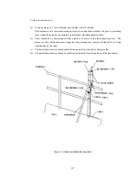
Avoid routing the antenna cable near other cables such as power cable,
transmission antenna cables, or radar waveguides. Close proximity to such
cables could cause interference (electronic “noise”) whereby the signal to the
receiver may deteriorate.
Criteria for site selection
(a) The distance from the magnetic compass should be at least 1 meter.
(b) The length of the grounding wire should be minimized.
(c) The installation location should be as free as possible from direct sunlight.
(d) The installation location should also be: free from excessive heat, moisture, and vibration; in
case of installation on the ceiling, free from the stagnant heat as well as the above, and; in case
of installation near a window, free from salt water spray as well as the above.
(e) The clearances as shown in the figure below should be confirmed.
The antenna cable, power cable, and grounding wire should be routed so as not to be in close
proximity with transmitter, radar, and other sources of electronic noise, as well as the cables of
these external units.
(Unit: )
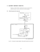
Fig. 3-1 Space required for receiver installation
inch
mm
Summary of Contents for NCR-330
Page 1: ...NCR 330 NAVTEX RECEIVER INSTRUCTION MANUAL...
Page 7: ...vi EXTERNAL VIEW OF EQUIPMENT...
Page 14: ...3 1 4 STRUCTURE Unit mm External diagram of the NCR 330 NAVTEX Receiver...
Page 16: ...5 1 5 OVERALL FLOW CHART DIAGRAM Overall Flow Chart Diagram of the NCR 330 NAVTEX Receiver...
Page 17: ...6 Overall Flow Chart Diagram of the NAW 330 NAVTEX Antenna...
Page 21: ...10 2 2 REAR PANEL View of the equipment with rear cover removed...
Page 23: ...12...
Page 31: ...20 Fig 3 5 2 Wiring the rear terminal board Only when the power unit is to be used...
Page 33: ...22 Fig 3 6 2 Wiring the rear terminal board Only when battery power is to be used...
Page 66: ...55 Fig 6 3 Removing the casing...
Page 72: ...61...


