13
CHAPTER 3
INSTALLATION
WARNING
Never carry out the receiver installation by a user.
Ask your nearest branch, business office or a dealer for inspection and repair.
3.1
FASTENING THE RECEIVER
3.1.1
Site selection
The receiver is designed so that it can be installed on either a desk, a wall, or the ceiling of the
vessel. Select an installation location that satisfies the criteria listed on the following page.
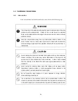
WARNING
Do not place the receiver unit on an unstable surface. If placed on an unstable
table or an uneven surface, it could fall and result in personal injury and/or
damage or malfunction of the unit.
Do not place heavy objects on the receiver unit. Failure to observe this
warning could result in the unit becoming unbalanced and thus causing injury if
it falls.
Do not place heavy objects on the power cable or the antenna cable. Failure
to observe this warning could result in fire, electrical shock, product trouble,
and/or receiver signal deterioration.
CAUTION
Do not expose to water or moisture. Placement on exposed decks or in humid
places may cause electrical shock or product malfunction.
Avoid exposure to direct sunlight, heat, moisture, and dust. Failure to do so
may cause fire, malfunction, and/or deterioration of print-out quality.
Summary of Contents for NCR-330
Page 1: ...NCR 330 NAVTEX RECEIVER INSTRUCTION MANUAL...
Page 7: ...vi EXTERNAL VIEW OF EQUIPMENT...
Page 14: ...3 1 4 STRUCTURE Unit mm External diagram of the NCR 330 NAVTEX Receiver...
Page 16: ...5 1 5 OVERALL FLOW CHART DIAGRAM Overall Flow Chart Diagram of the NCR 330 NAVTEX Receiver...
Page 17: ...6 Overall Flow Chart Diagram of the NAW 330 NAVTEX Antenna...
Page 21: ...10 2 2 REAR PANEL View of the equipment with rear cover removed...
Page 23: ...12...
Page 31: ...20 Fig 3 5 2 Wiring the rear terminal board Only when the power unit is to be used...
Page 33: ...22 Fig 3 6 2 Wiring the rear terminal board Only when battery power is to be used...
Page 66: ...55 Fig 6 3 Removing the casing...
Page 72: ...61...


