8
1:
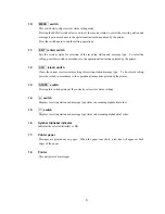
POWER lamp
Pressing the POWER switch activates the green POWER lamp to indicate that the power has been
turned on.
2:
POWER switch
Turns the receiver on and off.
3:
RECEIVE lamp
This lamp turns on during signal detection and blinks during message text receiving.
4:
TEST switch
Activates the receiver’s self-diagnostic function.
5:
DIMMER switch
Adjusts the brightness of the status lamps.
Each time the switch is pressed, the brightness changes in the following order:
High
→
Medium
→
Low
→
Off
This switch, however, does not change the brightness of the PAPER and
ALARM lamps described below.
6:
PAPER lamp
This orange lamp blinks to indicate that the equipment has run short of printer paper.
7:
FEED switch
Pressing this switch feeds printer paper from the printer.
Paper is fed, line by line, with each press of the switch. Pressing and holding it down feeds the
paper continuously.
8:
ALARM lamp
This red lamp blinks to indicate that an alert message is being received.
9:
ALARM OFF switch
This switch turns off the alarm that indicates that the equipment is receiving an alert message(s)
or running short of printer paper.
Summary of Contents for NCR-330
Page 1: ...NCR 330 NAVTEX RECEIVER INSTRUCTION MANUAL...
Page 7: ...vi EXTERNAL VIEW OF EQUIPMENT...
Page 14: ...3 1 4 STRUCTURE Unit mm External diagram of the NCR 330 NAVTEX Receiver...
Page 16: ...5 1 5 OVERALL FLOW CHART DIAGRAM Overall Flow Chart Diagram of the NCR 330 NAVTEX Receiver...
Page 17: ...6 Overall Flow Chart Diagram of the NAW 330 NAVTEX Antenna...
Page 21: ...10 2 2 REAR PANEL View of the equipment with rear cover removed...
Page 23: ...12...
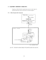
Page 31: ...20 Fig 3 5 2 Wiring the rear terminal board Only when the power unit is to be used...
Page 33: ...22 Fig 3 6 2 Wiring the rear terminal board Only when battery power is to be used...
Page 66: ...55 Fig 6 3 Removing the casing...
Page 72: ...61...


