


29
(b) Second character
This character identifies the type of message.
A: Navigational alert
B: Meteorological alert
C: Iceberg report
D: Search-and-rescue information
E: Weather forecasts
F: Pilot information
G: Decca information
H: Loran information
I: Omega information
J: Satellite navigational information
K: Electronic navigation equipment information
L: Navigational alert (Supplement to message A above)
V, W, X, and Y: Special services
Z: Indicates no information.
(c) Third and fourth characters
These characters denote the report number assigned to the message by the coast
station where the message originated.
The four-character identification code is stored in memory only when the message is
received at a character error ratio of 4% or less. When an incoming message has the
same identification code as one already stored in memory, it will not be printed.
The above, however, does not apply to report number ‘00’. For report number ‘00’, the
code is not held in memory and messages are printed each time they are received.
2)
Text
Text of the message
3)
End-of-message code
This code denotes the end of transmission of one message.
4)
End-of-message guidance
Denotes the end of the message itself. There are three types of guidance codes:
(a)
--- End of Message CER=
∗
.
∗
% ---
Indicates that message transmission ended normally with [NNNN].
(b)
--- Ended by 2 Alpha CER=
∗
.
∗
% ---
Indicates that the end-of-transmission code was received during message receiving.
(c)
--- Incomplete Message CER=
∗
.
∗
% ---
Indicates that message receiving was interrupted.
Summary of Contents for NCR-330
Page 1: ...NCR 330 NAVTEX RECEIVER INSTRUCTION MANUAL...
Page 7: ...vi EXTERNAL VIEW OF EQUIPMENT...
Page 14: ...3 1 4 STRUCTURE Unit mm External diagram of the NCR 330 NAVTEX Receiver...
Page 16: ...5 1 5 OVERALL FLOW CHART DIAGRAM Overall Flow Chart Diagram of the NCR 330 NAVTEX Receiver...
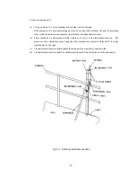
Page 17: ...6 Overall Flow Chart Diagram of the NAW 330 NAVTEX Antenna...
Page 21: ...10 2 2 REAR PANEL View of the equipment with rear cover removed...
Page 23: ...12...
Page 31: ...20 Fig 3 5 2 Wiring the rear terminal board Only when the power unit is to be used...
Page 33: ...22 Fig 3 6 2 Wiring the rear terminal board Only when battery power is to be used...
Page 66: ...55 Fig 6 3 Removing the casing...
Page 72: ...61...