16
3.2
FASTENING THE ANTENNA
3.2.1
Site selection
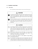
Select an installation location that satisfies the criteria listed on the following page.
WARNING
The connectors of the antenna cable and the case mounting section of the whip
antenna must be waterproofed. Failure to do so could cause fire, electrical
shock, and/or deterioration of the signal to the receiver due to moisture or faulty
electrical contact.
Keep the whip antenna away from any obstructions within a radius of one
meter. Failure to do so could cause injure due to contact with human body.
Antenna damage might result from possible contact with the human body or .
obstructions.
CAUTION
Avoid bundling the antenna of the NAW-330 together with any other antennas.
Failure to observe this caution may cause deterioration of the signal to the
receiver due to noise radiated from other antennas. Further, noise radiated
from the antenna of the NAW-330 could cause signal deterioration to other
equipment.
Avoid routing the antenna cable near other cables such as power cable,
transmission antenna cables, or radar waveguides. Noise induced to the
antenna cable could deteriorate the receiver signal.
Do not install the whip antenna in a place exposed to strong vibration.
Antenna damage could result.
The connectors of the antenna cable must be waterproofed. Further, the
antenna connectors of the NAW-330 float from the ship earth could cause turn
on the earth lamps due to contact with the ship earth use battery power source.
Summary of Contents for NCR-330
Page 1: ...NCR 330 NAVTEX RECEIVER INSTRUCTION MANUAL...
Page 7: ...vi EXTERNAL VIEW OF EQUIPMENT...
Page 14: ...3 1 4 STRUCTURE Unit mm External diagram of the NCR 330 NAVTEX Receiver...
Page 16: ...5 1 5 OVERALL FLOW CHART DIAGRAM Overall Flow Chart Diagram of the NCR 330 NAVTEX Receiver...
Page 17: ...6 Overall Flow Chart Diagram of the NAW 330 NAVTEX Antenna...
Page 21: ...10 2 2 REAR PANEL View of the equipment with rear cover removed...
Page 23: ...12...
Page 31: ...20 Fig 3 5 2 Wiring the rear terminal board Only when the power unit is to be used...
Page 33: ...22 Fig 3 6 2 Wiring the rear terminal board Only when battery power is to be used...
Page 66: ...55 Fig 6 3 Removing the casing...
Page 72: ...61...


