


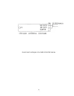


11
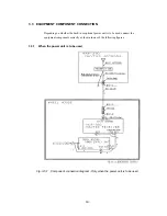
1:
High-impedance antenna terminal (HIGH-Z ANT)
Connect a wire antenna cable to this terminal.
2:
50-ohm antenna terminal (50OHM ANT)
Connect a wide-band antenna cable to this terminal.
3:
NAVTEX antenna terminal (ACTIVE ANT)
Connect the antenna cable of NAW-330 Active Antenna to this terminal.
4:
Key line terminals (BK+/BK-)
If needed, connect the key lines leading from the transmitter to be used to these terminals.
5:
External alarm buzzer terminals (EXT.ALARM/SIGNAL.GND)
If needed, connect an optional CGC-300A buzzer to these terminals.
6:
Grounding terminal (EARTH)
This terminal is for electrical grounding to the hull of the vessel.
7:
Power terminals (DC+/DC-)
Connect the power supply to these terminals.
The voltage range of the power supply is from 10.8 to 35.0 VDC.
8:
IRCS data input/output connector (IRCS)
This connector sends received messages to the Integrated Radio Communications System (IRCS)
for vessels and allows the NAVTEX Receiver to be set and controlled from the IRCS. Input and
output are of the current-loop specifications. Data formats comply with the JRC commands.
9:
ECDIS data output connector (ECDIS)
This connector sends received messages to the Total Navigator (ECDIS). Output is of the RS-
422A specifications. The data format complies with the JRC commands.
10:
Test terminals
These terminals are for in-factory testing only.
11:
Fuses
A pre-arcing fuse rated at 3.15 A is connected to each the DC(+) and DC(-) lines.
Summary of Contents for NCR-330
Page 1: ...NCR 330 NAVTEX RECEIVER INSTRUCTION MANUAL...
Page 7: ...vi EXTERNAL VIEW OF EQUIPMENT...
Page 14: ...3 1 4 STRUCTURE Unit mm External diagram of the NCR 330 NAVTEX Receiver...
Page 16: ...5 1 5 OVERALL FLOW CHART DIAGRAM Overall Flow Chart Diagram of the NCR 330 NAVTEX Receiver...
Page 17: ...6 Overall Flow Chart Diagram of the NAW 330 NAVTEX Antenna...
Page 21: ...10 2 2 REAR PANEL View of the equipment with rear cover removed...
Page 23: ...12...
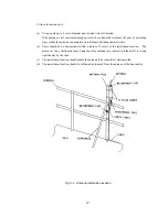
Page 31: ...20 Fig 3 5 2 Wiring the rear terminal board Only when the power unit is to be used...
Page 33: ...22 Fig 3 6 2 Wiring the rear terminal board Only when battery power is to be used...
Page 66: ...55 Fig 6 3 Removing the casing...
Page 72: ...61...