background image

Teaching Pendant Operation 

Desktop Robot JR3000 

3.1.3  Customizing Mode 

 
NOTE 
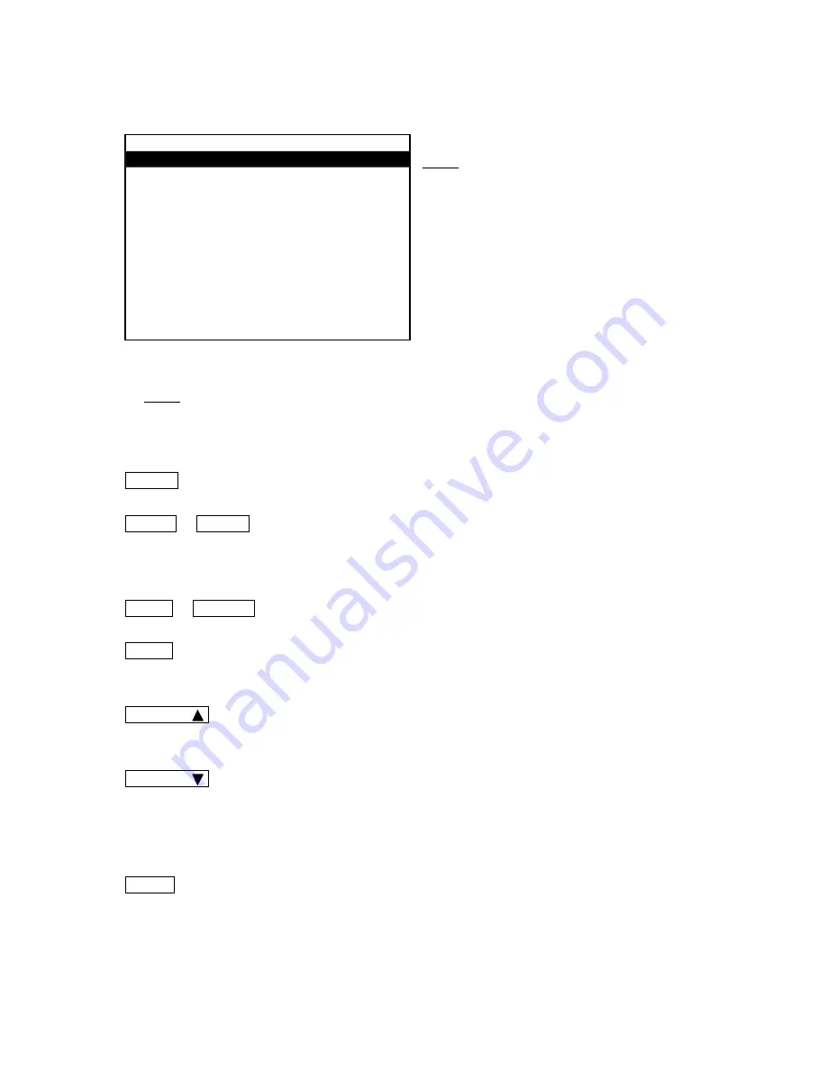
The screen shown to the left is the Customizing 
Mode menu after login. 


NOTE 
For  further  details  regarding  Customizing  Mode,  refer  to  the  operation  manual 

Functions  IV 

(Customizing)


  MODE   ···································  Displays the mode selection menu. 


  SHIFT    +    MODE   ·················· Press  these  keys  at  the  base  screen  to  switch  modes  in  the 

following order:   
Switch Run Mode 

Æ

 External Run Mode 

Æ

 Teaching Mode 


  CTRL    +    UTILITY   ·················  Displays the LCD language display menu. 


  SAVE   ····································  Saves C & T (customizing & teaching) data.   

Use this key to save C & T data. 


  CURSOR       ····························  Moves the highlight bar one line upward. This key is invalid if the 

first item on the first page is already highlighted. 


  CURSOR       ····························  Moves  the  highlight  bar  one  line  downward.  The  highlight  bar 

moves to the first line of the next page if the last line is highlighted. 
This  key  is  invalid  if  the  last  line  of  the  last  page  is  already 
highlighted. 


  ENTR   ····································  Displays the entry or selection screen for the highlighted item. 


Customizing Mode 

Teaching Mode Customizing 

Account 
Point Type Definition 
Variable Definition 
User Function Definition 
Alias Definition 
Additional Function Data Settings 
Point Job Settings 
PLC Settings 
Data Copy, Delete 


Base Screen Example: Customizing Mode 

20 

Summary of Contents for JR3000 Series

Page 1: ...always make sure you use the robot correctly In particular be sure to thoroughly read For Your Safety as it contains important safety information z After reading this manual store in a safe place that...

Page 2: ...t Quick Start Explains the actual operation of the robot by creating and running simple programs Teaching Pendant Operation Explains how to operate the robot via the teaching pendant PC Operation Expl...

Page 3: ...nd the robot will revert to its original settings Make sure that you save any changes to data and or settings Attention Attention Note The operation methods described in this manual are indicated as f...

Page 4: ...2 3 3 Entering Numbers 24 3 4 Entering Characters and Expressions 26 3 5 Position Entry 29 3 5 1 Manual Job 30 3 5 2 Copying Point Coordinates 31 3 5 3 JOG Mode 31 3 5 4 MDI Mode 35 4 UTILITY 38 4 1 T...

Page 5: ...Run Modes 58 5 PROGRAM SELECTION PRG NO Key 59 6 POINT RUN 61 7 EDITING EDIT Key 64 7 1 Point Editing 64 7 1 1 Inserting a Point 64 7 1 2 Deleting a Point 65 7 1 3 Block Editing 66 7 1 4 Common Block...

Page 6: ...hange Program Number 100 8 8 7 Delete All 101 8 8 8 Delete All Teaching Data 102 8 8 9 Reset Individual Program Settings to Default Values 102 8 8 10 Reset All Program Common Settings to Default Value...

Page 7: ...noring these safety guidelines and misusing the robot are classified by the following symbols This symbol indicates an imminent risk of serious injury or death This symbol indicates a risk of serious...

Page 8: ...adequate installation causes overheating and fire Make sure to power the unit within its rated current range Failure to do so causes electric shocks fires and unit malfunction Plug the power cord into...

Page 9: ...uch as the teaching pendant cable Failure to do so causes electric shock fire data loss and unit malfunction Do not attempt to disassemble or modify the unit Disassembly or modification causes electri...

Page 10: ...g the unit take safety measures such as setting up area sensors and an enclosure If there are no safety measures in place and someone enters the area of operation when the robot is running they may be...

Page 11: ...he cords and cables to the main unit Improper wiring causes unit malfunction or breakdown Be sure to secure the movable parts of the unit before transportation Failure to do so causes injury or breakd...

Page 12: ...points in Teaching Mode both the TEACH and RUN LEDs light up ERROR Red LED RUN Red LED TEACH Green LED LOGIN Green LED HOME Green LED NOTE The teaching pendant is optional From here onwards the descri...

Page 13: ...ordinates displayed on the LCD PRG NO Program Number Key Displays the program number input screen UTILITY Utility Key Displays the utility menu EDIT EDIT Key Displays the point edit menu Numerical Inp...

Page 14: ...Directional Key Moves the MT2 auxiliary axis in the direction MT2 MT2 Directional Key Moves the MT2 auxiliary axis in the direction CURSOR Cursor Left Key Moves the cursor to the left CURSOR Cursor R...

Page 15: ...he switch box optional Teaching Mode This mode creates programs Customizing Mode This mode creates data for composing programs Administration This mode is for administration and maintenance The mode c...

Page 16: ...e is not displayed The PTP speed override reduces the PTP speed by the percentage displayed this does not affect the CP speed Note this is not displayed when set to 100 Operation keys are disabled whi...

Page 17: ...n saving C T data 3 1 2 Teaching Mode NOTE The point settings screen may have multiple pages depending on the point setting and content When in Teaching Mode the TEACH LED lights up on the teaching pe...

Page 18: ...ey when changing the currently selected program or registering a new program SAVE Saves C T customizing teaching data Use this key to save C T data EDIT Displays the point editing screen Every point c...

Page 19: ...entered the new point entry screen will appear This key is invalid when the next point is not yet entered SHIFT CURSOR Displays the settings screen for the first point number 1 SHIFT CURSOR Displays a...

Page 20: ...Point type Push ENTR to display the point type selection screen Point Job Additional function data Push ENTR to display the numerical entry screen for the registered point job additional function dat...

Page 21: ...ing data Use this key to save C T data CURSOR Moves the highlight bar one line upward This key is invalid if the first item on the first page is already highlighted CURSOR Moves the highlight bar one...

Page 22: ...is invalid if the first item on the first page is already highlighted CURSOR Moves the highlight bar one line downward The highlight bar moves to the first line of the next page if the last line is h...

Page 23: ...e upward This key is invalid if the first item on the first page is already highlighted CURSOR Moves the highlight bar one line downward The highlight bar moves to the first line of the next page if t...

Page 24: ...are no more items to set the new position entry screen for the next point appears ESC Displays the previous menu or reverts to the base screen This key is invalid on the program number selection scree...

Page 25: ...is key within 0 5 seconds the value decreases by the minimum increment If you press this key for more than 0 5 seconds the value decreases every 0 2 seconds SHIFT CURSOR Increases the value at 10 time...

Page 26: ...hout the decimal point If the cursor is hidden the bottommost figure is deleted and the figures move one place to the right ENTR Sets the numerical value and returns the screen to the previous menu or...

Page 27: ...the letter B is entered If you want to enter the letters AB enter the letter A first and press the CURSOR key to shift the cursor to the right and then enter B Keys which have no character assigned su...

Page 28: ...d at the same time the character assignment type changes in the following order Roman uppercase Roman lowercase numbers symbols operators Roman uppercase However when entering names the operators assi...

Page 29: ...ter is deleted SHIFT DEL CLR Clears the entire character string F2 BFunc Displays a list of built in functions functions built into the robot in advance as operating functions This key is valid when t...

Page 30: ...DI Mode If already in the MDI mode each time F3 is pushed a screen for entering coordinates for each axis is displayed in this order X Y Z R X F4 INIT Executes mechanical initialization NOTE No matter...

Page 31: ...Number FUNC JOG MDI INIT FUNC F9 F10 F11 F12 Keys F0 F1 F2 F3 F4 F0 F1 F2 F3 F4 FUNC F1 F2 F3 F4 Key FUNC F5 F6 F7 F8 Keys F0 F1 F2 F3 F4 F0 F1 F2 F3 F4 Before using this function you need to set the...

Page 32: ...d are copied You can select points only within the currently selected program Enter 0 to copy the work home position coordinates 3 5 3 JOG Mode In JOG Mode position entry is done by moving the robot a...

Page 33: ...is at low speed As you continue to hold down the jog key the axis will gradually increase speed and move at medium speed When pushing a JOG key when moving the axis at low medium speed also hold the S...

Page 34: ...d the functions of the F1 F4 keys by pressing the F0 key the point jobs assigned to the keys are performed instead Manual job SHIFT UTILITY Displays the settings screen for the tool during teaching UT...

Page 35: ...Teaching Pendant Operation Desktop Robot JR3000 This is a sample diagram of the JR3204 Y Axis Y 0 Y X Axis X 0 X Z 0 Z Z Axis R Axis JR3000 Coordinate System 34...

Page 36: ...us and minus signs This key is invalid if a negative number is not possible NOTE The above 1 keys are called numeric keys SHIFT DEL CLR Clears the entire value The value becomes 0 DEL CLR Deletes the...

Page 37: ...does not light up when using the GO key to move the axes ESC This key is invalid when a new position is entered Returns to the point settings screen base screen when a position is modified SHIFT ESC G...

Page 38: ...point number coordinate values CTRL UTILITY Displays the language settings NOTE Axis movement in MDI Mode is not limited by the move area limit If a move area limit is required enter the positions us...

Page 39: ...ditions for each axis when moved by pressing the GO key JOG Function Set the moving speed for each axis when entering positions using the JOG Mode Tool for Teaching Enter the settings for tool data va...

Page 40: ...the Unit of Measurement You can select the unit of length displayed on the teaching pendant LCD Choose either millimeters or inches UTILITY Teaching Environment Settings Unit of Measurement Millimete...

Page 41: ...Mode Z Move Height Horizontal Move Pos n Z Up Distance Start Horizontal Z Down Distance Start Down Pos n Select the item you want to change and then enter the value TP GO Function PTP Speed 30 R Axis...

Page 42: ...item for which you want to specify speed distance The number entry screen for the selected item is displayed Enter and set the speed distance The speed distance entered here becomes the axes speed dis...

Page 43: ...hen teaching a program to perform a pick place operation if you set a point job number for closing the hand tool to the F1 key you can check during program teaching to see if the hand tool can actuall...

Page 44: ...nt job numbers press the F0 FUNC key on the position entry screen The indicators on the last line will change from FUNC JOG MDI and INIT to the point job numbers set to the F1 F2 F3 and F4 keys as sho...

Page 45: ...Settings Key Click Robot OFF TP Panel OFF Robot ON TP Panel OFF Robot OFF TP Panel ON Robot ON TP Panel ON Robot OFF TP Panel OFF No sound Robot ON TP Panel OFF Emits sound only from the robot Robot...

Page 46: ...Detailed Display to have a coordinate value display with one line and up to three decimal places per axis up to two decimal places for the R axis on the point settings screen The default setting is N...

Page 47: ...r is detected and you are on the data check results screen if you push any key other than the SHIFT CTRL or ESC keys the result data for the error point following the current error point is displayed...

Page 48: ...nance Example Previous Point Error Point PTP Evasion Point OK PTP Point CP Start Point Error Previous Point Error Point PTP Point PTP Point PTP Evasion Point PTP Evasion Point CP Start Point CP End Po...

Page 49: ...ates exceed the operating range or the move area limit of the robot an error occurs and the message Position is Out of Range is displayed when you perform a data check Correct the error by using one o...

Page 50: ...run standby screen as shown to the right Press the F4 START key The test run starts Check to see whether the program is performed the same as it was entered Press the F3 POINT key to perform a point...

Page 51: ...t switch to invalid if the robot is set to continuous playback as the only way to stop the robot with this combination is by an emergency stop 4 2 3 IO Connection Test UTILITY Test Menu IO Test Select...

Page 52: ...tion on PTP speed override please refer to 7 5 PTP Speed Override or 8 5 PTP Speed Override in the operation manual Basic Instructions NOTE If Program Number Switching Method in the All Program Common...

Page 53: ...t Test Run Fieldbus Check IO The Test Run Fieldbus Check IO screen is displayed Press the F4 START key to start the test run For the Test Run Fieldbus Check IO the test run is performed while displayi...

Page 54: ...emergency stop 4 2 7 Check IO Fieldbus UTILITY Test Menu Check IO Fieldbus Press UTILITY select Test Menu and then select IO Test Fieldbus The fieldbus input output statuses are displayed as a unit of...

Page 55: ...mory Ver 2 0 into the Memory Port to record robot data NOTE The USB memory device needs to be in FAT format The robot may not recognize some USB memory devices depending on the manufacturer You can us...

Page 56: ...to USB Memory Read from USB Memory NOTE Always make sure to insert remove the USB memory using the MEMORY Port screen Do not insert remove the USB memory while the message is displayed and the robot...

Page 57: ...ing data backup files in the DATA folder If you change the folder name the data cannot be read 4 3 2 System Software Updates and PS Data Model Setting Data Updates Create the predefined folder in the...

Page 58: ...Setting MEMORY Port Valid Invalid Setting If you set the MEMORY port to invalid the menus relating to the MEMORY port and auto update are no longer displayed Auto Update Valid Invalid Setting You can...

Page 59: ...ory 4 4 4 Run Modes When a teaching pendant is connected you can view error history by pressing the MENU key at the base screen and selecting Error History from the menu MENU Error History NOTE The di...

Page 60: ...not appear on the display F0 DEL key This displays a number entry screen for program deletion Enter the program number that you want to delete F1 COPY key This displays a number entry screen for the p...

Page 61: ...not as z or but as The following keys are enabled on the graph display screen CURSOR CURSOR Displays an existing program for the next largest number from the currently displayed program This key is d...

Page 62: ...c to wait for a start signal from IO 1 etc the robot will also wait for a start signal when running points in Teaching Mode Press the F4 P EXEC key on the point settings screen The robot runs the curr...

Page 63: ...a Cycle Mode is set to 1 Cycle Playback the robot runs the work home position if it is set to Continuous Playback it runs the first point However even when Cycle Mode is set to Continuous Playback if...

Page 64: ...again after making a point run on the final point in the program At this time if Job on End of Cycle in P EXEC is set to Valid the point job registered in Job on End of Cycle is executed If the progra...

Page 65: ...r the number that will come after you have inserted the point in the place you want EDIT Insert a Point When you select Insert a Point the new position entry screen appears Enter the position for the...

Page 66: ...ted P1 P4 P3 P2 P5 7 1 2 Deleting a Point Display the settings screen for the point that you wish to delete EDIT Delete a Point If you select Delete a Point the point currently displayed is deleted an...

Page 67: ...t all points in the program The block end number entry screen does not appear Press the F4 LAST key on the block end number entry screen The last point number in the program is entered You can set def...

Page 68: ...appears Select YES Each point that comes after the deleted points decreases by the number of points deleted Move Block Points You can move a block of points between given points in a program However n...

Page 69: ...reen appears Enter the Y direction moving distance of the copied block After entering the Y distance the copy times entry screen appears Enter the number of copies you want After entering the number o...

Page 70: ...et enter the Y offset Z offset and R offset in order Enter 0 if you do not want to move the block in a particular direction After entering the offset the offset is added to all points in the block and...

Page 71: ...the right appears Enter the coordinates of the mirror position for X or Y After entering the X Y mirror position a mirror copy is made and the screen returns to the block editing menu The copied point...

Page 72: ...e the center Y entry screen appears Enter the Y coordinate for the center of rotation After entering the Y coordinate the rotate angle entry screen appears Enter the rotation angle After entering the...

Page 73: ...le the block is rotated and copied and the screen returns to the block editing menu Always make sure you perform Data Check in Test Menu JOG Offset This designates two points uses the difference betwe...

Page 74: ...Block Settings If the block contains any point that the specified additional function cannot be set to PTP conditions set to CP points etc that point is not affected Press the EDIT key on the point se...

Page 75: ...ommon Line Speed Settings from the common block settings menu and enter the speed you want The maximum line speed is 850mm s If a larger number is entered the speed is set as 850mm s The maximum line...

Page 76: ...that you want to set and enter that number NOTE Please refer to 8 4 Additional Function Data for more information regarding additional function data F0 DEL key This displays the delete additional fun...

Page 77: ...ct Convert to Relative Coordinates to convert all the point coordinates in the currently selected program into relative coordinates Specifically deduct the Point 1 values for the X Y Z and R axes from...

Page 78: ...int Data Point Data Program Data 01 02 Last Point PTP Condition CP Condition Tool Data Pallet Routine Work Adjustment Execute Condition Additional Function Data Used in Run Modes PLC Program All Progr...

Page 79: ...This setting is fixed at 7kg 2 Only for JR3000E Series 3 Only for robots equipped with auxiliary axis functions 8 2 Common Data Depending on the settings in Customization Mode Common Data is not displ...

Page 80: ...are set in program data Use these when you want to change the settings between designated points only 3 Tool Data These have the same contents and items as those which are set in program data Use the...

Page 81: ...registered additional function number list Select a number from the list to display the additional function data settings screen with no content entered F3 LIST key This displays the registered additi...

Page 82: ...you wish to modify according to either of the following methods Method 1 On the point settings screen MENU Point Job Settings Enter the point job number Method 2 On the point settings screen Job befo...

Page 83: ...isplays the unregistered point job number list Select a number from the list The new entry or selection screen for point job data is displayed Enter the commands or parameters With Method 2 pressing t...

Page 84: ...er Once you select a command the parameter entry or selection screen appears Depending on the command there are commands with no parameters and those which require multiple parameters Enter or select...

Page 85: ...row and the column the displayed data entry screen appears Enter sv 24 sv 25 Additionally when entering a number as a parameter you can select a variable or an expression instead of a value if EXP is...

Page 86: ...command that you want to change Press the EDIT key and select Change Command The command category selection screen appears Select the command category and the command that you want to change and enter...

Page 87: ...the block end number entry screen appears Enter the last number of the command block After entering the block end number the command block is deleted and the screen returns to the settings screen The...

Page 88: ...y screen appears Enter the destination command number where the command block is to move After the destination number is entered the block is moved in front of the entered number Once the block is mov...

Page 89: ...the command number to where you want to copy the block After entering the destination number the block is moved in front of the entered number Once the block is copied the screen returns to the settin...

Page 90: ...be entered when using the teaching pendant When using the PC the maximum number of characters is 40 depending on the character type However up to 36 characters the maximum number of characters per lin...

Page 91: ...to display After you enter the command number a settings screen which includes the command sections of the entered number is displayed 8 6 PLC Programs A PLC program is a set of logical operation com...

Page 92: ...d PLC program number list Select a number from the list The selected PLC program data settings screen content not yet entered appears F3 LIST key This displays the registered PLC program number list S...

Page 93: ...ion and 3 3 Entering Numbers in this manual 8 8 Teaching Data Copy Delete Conversion 8 8 1 Program List Use this when you want to check to which program number a certain program is registered Key and...

Page 94: ...Tool Data Pallet Routine Data Copy Pallet Routine Data Workpiece Adjustment Data Copy Workpiece Adjustment Data Execute Condition Data Copy Execute Condition Data Point Job Data Copy Point Job Data PL...

Page 95: ...stered number list You can also select the program data you want from this list If the destination number already contains data a copy confirmation screen appears If you select YES the data is overwri...

Page 96: ...Condition Data Many Tool Data Copy Tool Data Many Pallet Routine Copy Pallet Routine Data Many Workpiece Adjustment Copy Workpiece Adjustment Many Execute Condition Copy Execute Condition Data Many Po...

Page 97: ...er list You can also select the data you want from these lists The data is copied within the range of destination data number S destination data number E The copy source cannot be included in the dest...

Page 98: ...Condition Data Delete Execute Condition Data Point Job Data Delete Point Job Data PLC Delete PLC Data Select Delete xxx to display the delete number entry screen as shown to the right Enter the number...

Page 99: ...tion Data Many Tool Data Delete Tool Data Many Pallet Routine Delete Pallet Routine Data Many Workpiece Adjustment Delete Workpiece Adjustment Many Execute Condition Delete Execute Condition Data Many...

Page 100: ...want to delete is entered the delete confirmation screen is displayed Select YES to perform the delete operation Select NO to return to the delete number entry screen Press the F3 LIST key on the del...

Page 101: ...a program already exists for the selected destination number the copy confirmation screen appears If you select YES the program is overwritten If you select NO the screen returns to the source program...

Page 102: ...ta Delete All Pallet Routine Data Workpiece Adjustment Data Delete All Workpiece Adjustment Execute Condition Data Delete All Execute Condition Point Job Data Delete All Point Job Data PLC Data Delete...

Page 103: ...b data 501 1000 additional function data 51 100 and PLC programs 51 100 are included in Customizing Data These cannot be deleted through this operation MENU Teaching Data Copy Delete Conversion Delete...

Page 104: ...nformation 8 8 11 2 Point Position Conversion Move Rotate By designating two points at the conversion source standard and the two corresponding points at the conversion destination you can perform par...

Page 105: ...from the 2 point position conversion menu The screen shown to the right is displayed Select the point range that you want to convert Selecting Convert All Position Data converts the following coordina...

Page 106: ...mber and the block end number the following coordinates are converted The position coordinates of points within the specified block of the currently selected program 8 9 PTP Speed Override The PTP spe...

Page 107: ...e screen Please do not turn the robot s power OFF when saving Data may be corrupted The save operation overwrites the registered data Note that you cannot restore overwritten data If you want to back...

Page 108: ...function as a specialized application model If the specialized application data is deleted by mistake refer to 2 4 Transmitting the Robot System Software in the operation manual Maintenance and send t...

Page 109: ...e backlight ON ON with Key Pushing a key on the teaching pendant turns the backlight ON ON at Start A start command turns the backlight ON Always OFF The backlight is normally OFF in Run Mode Wait Tim...

Page 110: ...ngs Back Light Auto OFF Clear All C T Data Diagnostic Mode Mechanical Adjustment Mode Version Information Clock Settings C C Ethernet Settings Fieldbus Settings MEMORY Port Settings Clear Error Histor...

Page 111: ...Horizontal Move Pos n Z Up Distance Start Horizontal Z Down Distance Start Down Pos n Tool Data Move Area Limit Restart Method After Pos Offset JR3000E Series only Workpiece Mass JR3200 does not have...

Page 112: ...multaneously X before Y Y before X Valid Invalid G G Valid Invalid Teaching Mode Customizing Load at Start FieldBus Fieldbus Function Assignment Fieldbus Expansion IO Function Invalid Valid Account Ba...

Page 113: ...ete All CP Condition Data Copy Pallet Routine Data Delete Pallet Routine Data Delete All Pallet Routine Data Workpiece Adjustment Execute Condition Copy Execute Condition Data Delete Execute Condition...

Page 114: ...or the contents of this manual may be modified without prior notice to improve quality No part of this manual may be reproduced in any form including photocopying reprinting or translation into anoth...

Reviews: