File Version: 3.2
16
/
62
JAKA C Series Hardware User Manual
Chapter 3 Quick Start
Before reading this chapter, ensure that you have read in detail and fully understood the safety specifications
in Chapters 1 and 2.
This chapter will introduce the basic components and use methods of JAKA collaborative robots as a
preliminary understanding of the robot. For detailed mechanical electrical specifications refer to other chapters.
3.1
Overview of Robot Components
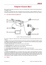
Figure 3-1 Overview of robot components
As is shown in Figure 3-1, JAKA robot use a wireless interconnection and requires the following components
in its use:
1.
Robot:
The main moving component to make movements as user desires. Ring-shaped indicators, buttons
for dragging and programming, and an IO interface for connecting tools (the TIO interface) are also arranged
at the end of the body to indicate the robot’s state.
2.
Robot connection cable:
Connect the robot and the control cabinet.
3.
Operation terminal:
The equipment for users to program, set parameters, etc.
4.
Control stick:
Power on/off and enable on/off the robot, etc.
5.
Control cabinet power supply cable:
Provide power supply to the control cabinet.
6.
Control cabinet:
The control cabinet includes the core computing components and various electrical
interfaces.
7.
Router and network cable:
The control cabinet comes with a wireless module that allows the operation
terminal to be connected to the wireless LAN of the control cabinet (the wireless network name is the control
cabinet number) to operate and control the robot. It is also accessible to connect the network port of the control
cabinet to the router and the operation terminal to the wireless network of this router at the same time. It is
recommended to configure a separate router for the robot to prevent conflicts with other devices.
3.2
Robot

