File Version: 3.2
48
/
62
JAKA C Series Hardware User Manual
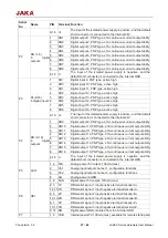
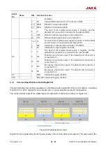
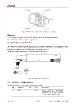
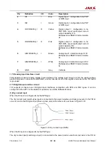
Pin
Definition
I/O
Color
Description
2
DI1
I
Blue
Digital input 1: configurable to be PNP
or NPN input
3
DI2
I
Green
Digital input 2: configurable to be PNP
or NPN input
4
DO1/RS485A_1
O
Yellow
Digital output 1: configurable to be
PNP, NPN, or push-pull output; current
output capability ≤1A
Multiplexed as RS485 Communication
A+
5
DO2/RS485B_1
O
Pink
Digital output 2: configurable to be
PNP, NPN, or push-pull output; current
output capacity ≤1A
Multiplexed as RS485 Communication
B-
6
AIN1/RS485A_2
I
Brown
Analog input 1: detection range 0-10V
Multiplexed as RS485 Communication
A+
7
AIN2/RS485B_2
I
White
Analog input 2: detection range 0-10V
Multiplexed as RS485 Communication
B-
8
GND
-
Grey
Cathode
1. TIO analog input interface circuit
TIO supports 2-channel analog voltage input interfaces. The voltage input range is 0-10V, the analog voltage
positive terminal is connected to AIN1/AIN2, and the internal circuit of the negative terminal on the TIO board
is grounded.
2. TIO digital input interface circuit
TIO supports 2-channel user DI digital input interfaces, compatible with NPN and PNP types. It can be
configured in the APP. For the details of operation, see JAKA Software Manual.
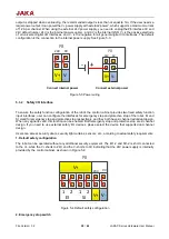
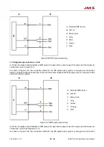
(1) Dry contact input
When the DI input is configured to be the NPN type:
The dry contact input (switch-type input) is connected to the power negative electrode (gray wire) in the TIO at
one end, and to the DI digital input (blue or green wire) at the other end, as shown in Figure 5-19.
Figure 5-19 Dry contact input (NPN)
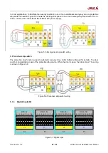
When the DI input is configured to be the PNP type:
The dry contact input (switch-type input) is connected to the power positive electrode (red wire) in the TIO at


