File Version: 3.2
47
/
62
JAKA C Series Hardware User Manual
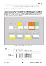
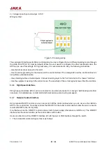
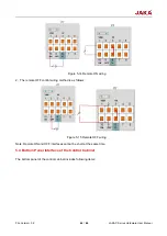
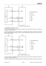
Figure 5-17 Definition of the robot connection cable interface
Warning:
1. It is forbidden to disconnect the robot cable when the robot is not completely powered off.
2. It is forbidden to extend or modify the original cable.
5.5
Tool Input and Output Interface
The tool input and output interface is referred to as TIO, installed on the side of the tool flange of the robot,
which includes two digital inputs, two digital outputs and two analog inputs, and can multiplex the two-channel
RS485 signal at the same time. For the definition of the interface, see 5.5.1:
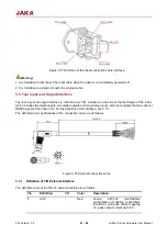
The definition and specifications of the connection wires are as follows.
Figure 5-18 External connection wires
5.5.1
Definition of TIO External Interface
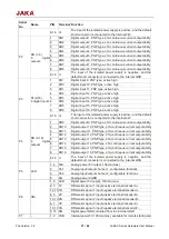
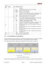
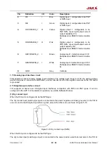
The definition table of the TIO V3 external interface is as follows:
Pin
Definition
I/O
Color
Description
1
+24V
-
Red
Anode,
24V/12V
(switchable);
configuration of enabling or shutdown
functions; continuous current capacity
1A; peak output current up to 2A.

