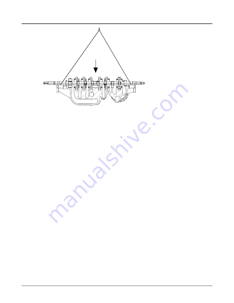
Figure 75: Installing the rotor
4.
Position the sling so that both loops around the shaft fall approximately at the seal diameter and in
front of the seal chambers (220, 221).
5.
Lower the rotating assembly, making sure all stationary parts fit into the groove locks.
6.
While maintaining tension on the rotating assembly, slide the lower half of all stage rings (144), the
center bushing (155), and the diaphragm (146), if applicable, into the lower half of the casing.
7.
Assemble the upper half of each component and tighten the socket head capscrews.
8.
You must center the rotating element inside the casing whenever the bearings are replaced:
a) Push the rotating element towards the coupling end until it stops.
b) Measure the distance from the thrust bearing shoulder on the shaft to the bearing housing face
on the casing.
c)
Pull the rotating element towards the thrust end until it stops.
d) Again, measure the distance from the thrust bearing shoulder on the shaft to the bearing hous-
ing face on the casing.
The difference between the two measurements is the total travel of the rotating element.
e) Calculate the average of these dimensions.
f)
Measure the shoulder depth on the inboard cover (160) and subtract the calculated average di-
mension.
The result is the spacer (217) thickness required to properly center the rotating element.
g) Remachine the spacer as necessary making sure that both faces are parallel within 0.025 mm |
0.001 in.
6.6.3 Confirm the seal chamber runout
The bearing housings are doweled to the casing (100) during the original build. However, to assure the
correct running position of the shaft, use the following procedure to confirm the seal chamber runout be-
fore installing the cartridge mechanical seals:
1.
Install the old bearings on the shaft and bolt the bearing housings to the casing.
2.
Mount the dial indicator on the shaft (122). Rotate the shaft (122) so that the indicator rides along
the seal chamber bore for 180°.
3.
If the total indicator reading exceeds 0.127 mm | 0.005 in., determine the cause and make correc-
tions. The bottom reading must be 0.0635 mm | 0.0025 in. or less.
For further instructions see Align the rotor.
6.6 Reassembly
Model 3600 i-FRAME API610 11th Edition / ISO 13709 2nd Edition to current API BB3 Multi-Stage, Axially Split Installa-
tion, Operation, and Maintenance Manual
101
Summary of Contents for GOULDS PUMPS 3600 i-FRAME
Page 2: ......


