70
Ioline FlexJet Service Manual
Step 4: Remove the logic board cover
1.
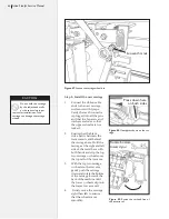
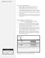
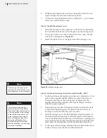
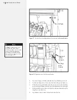
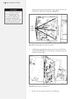
Remove the four screws that hold the sheet metal logic board
cover plate. (
Figure 56
.)
2.
Put static strap on. (
See
Caution
in margin on page 69.
)
Loosen this
9
/
64
-in screw
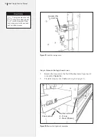
Figure 55.
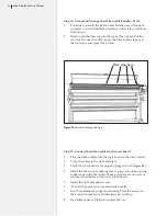
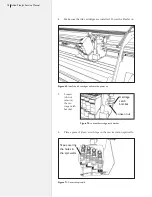
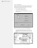
Install the carriage cover.
Figure 56.
Remove the logic board cover plate.
Short screw
Remove screws
2 - Front
2 - Rear (Shown)
The logic board cover will
swing down when the last
screw is removed. Make
sure to support it with one hand
and let it slowly rotate.
Caution
Summary of Contents for FlexJet
Page 1: ...Service Manual Ioline FlexJet ...
Page 3: ...Service Manual Ioline FlexJet ...
Page 4: ......
Page 8: ......
Page 12: ......
Page 60: ...60 Ioline FlexJet Service Manual This page intentionally left blank ...
Page 90: ...90 Ioline FlexJet Service Manual This page intentionally left blank ...
Page 96: ...96 Ioline FlexJet Service Manual This page intentionally left blank ...

