background image

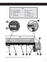
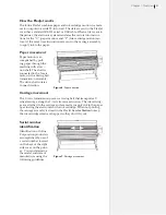
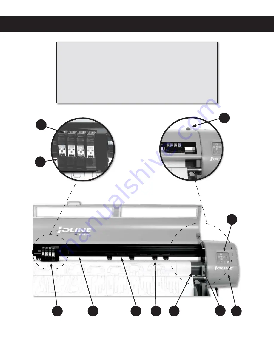
Figure 4. 

The Ioline FlexJet Printer front view close-up (safety cover lifted for clarity.)

R.

  Ink Cartridge Stall

S.

  Cartridge Stall Latch

T.

  Pinchwheel Lever

U.

  Keypad

V.

  Service Station 

(Beneath Cover)

W.

  Take-up Sensor

X.

  Platen

Y.

  Pinchwheel

Z.

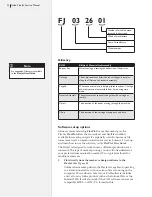
  Drive Shaft Marker

aa.

  Traverse

ab.

  Carriage Assembly

KEY

R

U

Y

X

ab

aa

S

V

T

W

Z

xviii

Summary of Contents for FlexJet

Page 1: ...Service Manual Ioline FlexJet ...

Page 2: ...every effort to make the FlexJet easy to operate maintain and repair It is the responsi bility of the operator of the printer to monitor the performance of the printer and maintain it in proper working condition by following the instructions in this manual and in the FlexJet User Guide and to follow all safety precautions and warnings that are described in these publications Ioline Corporation is ...

Page 3: ...Service Manual Ioline FlexJet ...

Page 4: ......

Page 5: ...9 LED lights on the keypad 36 Figure 20 Keypad LED error codes 36 Figure 21 The correct paper feeding path on the Ioline FlexJet Printer 42 Figure 22 HP cartridges have an ink level indicator 44 Figure 23 The ink cartridge is dirty dry or empty 44 Figure 24 The ink cartridge requires cleaning 45 Figure 25 Damaged and dirty print cartridge 45 Figure 26 Use a deliberate frame gap to help calibrate 4...

Page 6: ...the ribbon cables 71 Figure 59 Make a loop in the ribbon cable to the left of the carriage 72 Figure 60 Carriage installation 73 Figure 61 The carriage belt tensioner 73 Figure 62 Install the carriage cover 74 Figure 63 There should be a small gap in the ribbon cable loop 75 Figure 64 The loop in the cable should not touch the left endplate 75 Figure 65 Secure the sleeving with tape 76 Figure 66 R...

Page 7: ...plug connections to the board 84 Figure 84 Carefully remove the logic board 84 Figure 85 Inspect the connections to the logic board 85 Figure 86 Remove the keypad screws and bracket Unplug the keypad cable 87 Figure 87 Tighten the screws on theY Axis transmission 88 ...

Page 8: ......

Page 9: ...et works 21 Paper movement 21 Carriage movement 21 Serial number identification 21 Glossary 22 Software setup options 22 Power on 24 Installing FlexPlot and the Control Center 24 The FlexJet Control Center 25 Overview 25 Changing system settings 25 Control Center menu bar features 26 File 26 Communications 26 Tools 26 Help 26 Control Center menu options 27 SoftwareVersion 27 Cartridge Count 27 Get...

Page 10: ...dge calibration 46 Calibration overview 46 Cartridge alignment 46 Adjusting the cartridge alignment value 47 Motion adjustment 48 Frame gap 48 Unexplained frame gaps 49 Ink cartridge stall problems 50 Noisy carriage movement 50 Mechanical electrical and electronic diagnostics 51 No power to the FlexJet 51 Electrical problems 52 Troubleshooting sensors 52 General mechanical electrical issues 53 Sim...

Page 11: ...e Service Station 77 Logic Board Procedures 83 Logic board replacement 83 Updating the firmware 86 Keypad procedures 87 Keypad replacement 87 Y Axis procedures 88 Y Axis belt adjustment 88 X Axis procedures 89 Chapter 5 Parts Drawings FlexJet BOM Bill of Materials 91 Ioline FlexJet Exploded view 94 Ioline FlexJet Electronics view 95 Index ...

Page 12: ......

Page 13: ...ed all subsystem testing or replacement procedures must be performed with the FlexJet turned off and the power cord removed from the rear panel to avoid the pos sibility of electrical shock n Before beginning any subsystem testing or replacement proce dure make sure that the FlexJet is on a flat stable clean and dry surface n Keep fingers hair and clothing well clear of the FlexJet whenever moving...

Page 14: ...ber when it leaves the factory The warranty period is based on the serial num ber of the unit and extends from the date of manufacture up to 12 months plus an extra 3 months for shelf life Making the total war ranty period 15 months from the date of manufacture For warranty service the end user must work through their dealer Ioline Customer Service is available to assist Authorized Dealers with cu...

Page 15: ...ot User Guide Design software set up guides FlexPlot User Guide Maintenance FlexJet User Guide Basic troubleshooting FlexJet User Guide Advanced troubleshooting for qualified service personnel FlexPlot Service Manual Specifications part names drawings FlexPlot Service Manual What s in this Service Manual The FlexJet Service Manual provides extensive product specifica tions testing and repair proce...

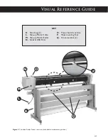
Page 16: ...B Safety Cover C Right End Cover D Take up Motor E Stand Leveling Foot F Feed Roll G Take up Shaft H Paper Hub 2 I Feed Shaft J Support Block 2 KEY Figure 2 The Ioline FlexJet Printer front view E A B C F D G xvi J I H ...

Page 17: ...e Ioline FlexJet Printer rear view head tilted in maintenance position K Stand Leg 2 L Take up Motor Cable M Take up Motor Outlet N Serial USB Ports O Power Switch and fuse P Platen Leveling Foot Q Cross member 3 KEY L M N O xvii Q P K ...

Page 18: ...ety cover lifted for clarity R Ink Cartridge Stall S Cartridge Stall Latch T Pinchwheel Lever U Keypad V Service Station Beneath Cover W Take up Sensor X Platen Y Pinchwheel Z Drive Shaft Marker aa Traverse ab Carriage Assembly KEY R U Y X ab aa S V T W Z xviii ...

Page 19: ...ndle many different printing operations up to 72 inches wide and 600 yards long Three industry standard printer languages HPGL 7475 and DM PL are supported The Ioline FlexJet also supports direct cable connection from many popular programs such as PAD Scanvec Optitex Polytropon Ioline IPS software and other applications Supported languages Language Application HPGL Direct from software or Ioline F...

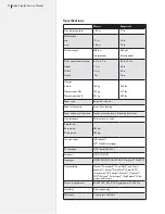
Page 20: ...ition Front floor loading Paper take up roll position Ergonomic waist level off loading from front Line thickness Thin normal or thick Resolution Best mode Draft mode 600 dpi 300 dpi Ink cartridges Off the shelf HP 51645A cartridges PC interface USB Serial RS 232 Protocol HPGL DM PL Languages DM PL DXF HP GL HP GL 2 MicroJet STD ASTM Compatibility Gerber Accumark MicroMark and Micro dynamics Assys...

Page 21: ...is motor with a timing belt transmisison assembly The drive shaft rotates in one direction Carriage movement The Y Axis transmission powers a timing belt that transports a V wheel carriage along the Y Axis traverse extrusion The ink cartridg es are attached to the carriage and are made to apply ink to the paper by actuating the electronics of the ink cartridge When not printing the carriage assemb...

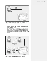
Page 22: ...FlexJet FlexPlot offers the most robust and flexible workflow available for creating output It s especially useful when many file formats are used a common situation for service bureaus To set up and learn how to use the software see the FlexPlot User Guide The FlexJet is designed to work in many different production envi ronments The type of marker printing you do will often determine your prefer...

Page 23: ... 6959 STD CAD Software HPGL DM PL Alternate Configuration CAD Software FlexPlot 2 Use FlexPlot software to convert files before sending them to the FlexJet for output The FlexJet includes the FlexPlot software which will convert many different files into a format that is compatible with the FlexJet It also provides an advanced marker queue manage ment system and other tools to optimize the perform...

Page 24: ...e for adjusting parameters to optimize printer performance The printer comes with a CD ROM which has Microsoft Windows 98 2000 XP versions of the programs as well as PDF user guides and the required Adobe Acrobat reader 1 Power on the computer and Windows 2 Insert the Ioline CD ROM into the CD ROM drive usually D 3 The installation program should start automatically If it does not a Select the Sta...

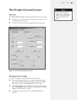
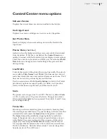
Page 25: ... from the computer n Provides an interface to send completed files to the printer Changing system settings A variety of settings are adjustable to fit specific needs n Make sure the printer power is on and that the initialization process is complete The carriage will park the keypad OK light will turn red and the Square light will turn green n The Screen Menu displays the primary settings that are...

Page 26: ... Machine ID Resets the machine serial number A unique key code only available from Ioline customer service is re quired It is usually only necessary if the main logic board is changed Size Calibration Allows adjustment of the size cali bration settings See the FlexJet User Guide for more details Set Machine ID Stores the printer serial number in permanent memory This step is required for upgrading...

Page 27: ... use more ink to produce higher contrast lines Used in conjunction with the Quality Setting see below the FlexJet provides six options for output quality to enable you to produce clearly visible lines using the least possible amount of ink Scale The printer scale ranges from 1 to 999 The factory default Scale is 100 A scale set to 50 prints at half size Changes do not take effect until the Set Sca...

Page 28: ...es 600 DPI A lower DPI setting uses less ink by creating a fainter line Higher DPI uses more ink but makes a darker line Use this setting in conjunction with the Line Width see above to find a bal ance between saving ink and making clearly visible lines Measurement Units Choose between English or Metric units for settings display ...

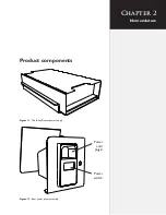
Page 29: ...Chapter 2 Nomenclature Figure 11 The Ioline Flexjet power supply Figure 12 Rear power panel assembly Power cord plugin Power switch Product components ...

Page 30: ...ce Manual Figure 15 Ink cartridges HP 51645A Figure 13 Service Station assembly Servo motor Carriage stop adjustment screw Cartridge wipers Cartridge caps Cartridge spit wells Figure 14 Pinchwheel assembly Wheels Replaceable ...

Page 31: ...coder X Axis encoder Take up encoder Service station encoder Serial port Ribbon cable socket Y Axis motor power X Axis motor power Take Up motor power Service Station motor power Main power Fans 1 2 3 Y axis encoder X Axis encoder Take up encoder Service station encoder Serial port Keypad Secondary sensor Ribbon Cable Socket USB port USB port Take up Sensor Keypad Secondary sensor Take up Sensor ...

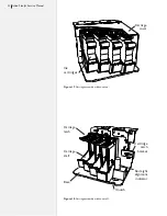
Page 32: ...vice Manual Figure 17 Carriage assembly with cover on Carriage cover Figure 18 Carriage assembly with cover off Ink cartridges Cartridge catch bracket Red Light alignment indicator Base Carriage stall Carriage latch V notch ...

Page 33: ... between the machines and the PC is connected correctly The information in this chapter begins with the simplest and most common issues and progresses to more complex and invasive trou bleshooting If you are unable to resolve a problem after consulting this manual fill out the Diagnostic Record at the end of this chapter then contact Ioline Customer Service Error messages Error messages that are s...

Page 34: ...esolve the problem confirm that FlexJet Control Center is displayed in the menu bar of the program If it is not obtain the correct version from Ioline Fatal Error COM port pointer is NULL Unable to recover A serious internal failure in the program or Windows has occurred Close all programs restart Windows then start the Control Center program Unable to change FlexJet baud rate Do you wish to chang...

Page 35: ... recommended that you update it as soon as possible but it is not required This program will work with new and old firmware Firmware upgrades are available from Ioline Customer Service at 425 398 8282 PST USA The firmware in the FlexJet is obsolete An upgrade is highly recommended Contact Ioline Customer Service to obtain the software and instructions The identification numbers for this board have...

Page 36: ...ion jam OFF R Y Blink OFF Buffer Overflow Y Blink OFF R OFF Init from EPROM failed OFF R R OFF File syntax error Y Blink Y Blink Y Blink OFF Printer ready to receive firmware Y Blink OFF OFF OFF Motors off System Stop Legend G Green light R Red light Y Yellow light Y Blink Blinking yellow light OFF Unlit Figure 20 Keypad LED error codes Keypad error codes Figure 19 LED lights on the keypad If keyp...

Page 37: ...r communications port on the computer 2 Change the computer COM port settings to match the FlexJet s serial communications settings See Serial Communication below Serial communication The serial port on the FlexJet has an adjustable baud rate Available speeds are 9600 19200 38400 57600 and 115200 It is critical that the FlexJet Control Center FlexPlot or design software use the same baud rate that...

Page 38: ...e Gap setting is incorrect 3 Carriage electronics or cables are damaged 4 Ink cartridge is dry Solution 1 Remove and reinstall ink car tridge 2 Use the Control Center to adjust frame gap as shown in the Routine Maintenance chapter of the FlexJet User Guide 3 Contact Ioline customer service 4 Clean or replace cartridge The printer does not complete the marker Cause 1 Outdated software 2 The frame p...

Page 39: ... Guide to reset paper align ment Make sure the front silver dancer bar is BELOW the front optical sensor before plotting 6 Make sure the distance between the print heads and platen surface is the same at the right center and left side of the printer Adjust the platen levelers as described in the FlexJet Quick Start Guide if necessary 7 Use the Control Center to check the firmware version and ensur...

Page 40: ...der rear cross member Solution 1 Change the paper roll 2 Make sure nothing is touching the feed roll and that the rear top bar rotates freely 3 Clean then lubricate the feed shaft block Use the included white lithium grease 4 Load paper straight as described in the Operation chapter of the FlexJet User Guide 5 Adjust paper to go between the front and rear cross members Gap between each scan Cause ...

Page 41: ... or Ioline Customer Service Pauses during printing Cause 1 Vector density is very high due to fine detail or the design soft ware is not using fonts embed ded in the printer 2 Communication baud rate is set very low 3 Frame length is too big Solution 1 Reduce vector density use em bedded printer fonts or increase communication baud rate 2 Increase baud rate from the minimum of 9600 baud to the def...

Page 42: ...Common situations that cause paper tearing while the FlexJet is operat ing include n The paper was incorrectly loaded in the machine n The rear heavy dancer bar was not loaded in the FlexJet after the paper was loaded Figure 21 represents the proper paper path The diagram on the left shows the paper after it is inserted properly and taped to the take up shaft The illustration on the right shows th...

Page 43: ...inkled or torn in any way It may cause paper jams n Make sure the pinchwheels are spaced across the paper as out lined in the FlexJet User Guide n The pinchwheels should never be positioned over bearings on the drive shaft as paper tearing and bunching will occur Verify that the pinchwheels are positioned over treads e g under the white markers affixed to the traverse n Check to make sure that the...

Page 44: ...it is black then the cartridge is empty Replace it with a new one 3 Remove the cartridge s and manu ally clean the print head with a de ionized water moistened lint free cloth See Cartridge Maintenance and Handling in the FlexJet User Guide 4 Plot on higher quality or undamaged free of wrinkles and bubbles paper 5 Use genuine HP 45 cartridges as recommended by Ioline 6 Recalibrate cartridges as de...

Page 45: ...will go bad for no apparent reason The cartridge may look perfect and be full of ink but it will not plot If this occurs first try pressing the Clean button on the keypad Install a new cartridge and the tests to see if this fixes the problem If this has no effect remove clean inspect for damage then test If the cartridge fails again replace it Broken circuit from mishandling ...

Page 46: ... head machines cartridge calibration is not neccessary Motion Adjustment Aligns side to side each pass of the car riage with the next pass Frame Gap Aligns from top to bottom each pass of the carriage Cartridge alignment Cartridge alignment will align the ink cartridges with each other This adjustment is only good for 2 or more heads A one head FlexJet does not need ink cartridge alignment Figure ...

Page 47: ...nt window to bring the two lines into alignment It is not necessary to adjust cartridge 1 Figure 27 The Cartridge Calibration window in the Control Center Figure 29 Increase the alignment value for cartridge 2 to improve line quality Figure 30 Decrease the alignment value for cartridge 2 to improve line quality Figure 28 The Cartridge Alignment dialog box Start with a frame gap of 30 and all cartr...

Page 48: ...line too late Visu ally this appears as if the line drifts to the right as shown in Figure 32 Mo tion Factor set too high results in drift to the left Frame gap The frame gap is defined as the space between each pass Use the Frame Gap window to make adjustments and elimi nate the gap Figure 32 The heads are drawing the lines too late on this plot Scan Scan Poor motion adjustment Direction of carri...

Page 49: ...aps on the plot One Scan Frame Gap Try releveling the FlexJet to see if this corrects the problem The FlexJet Quick Start Guide provides detailed instructions You ll need to locate the height adjusting spacer in the Acces sory Kit for this task If the leveling procedure does not cor rect the problem see Ink cartridge stall problems later in this chapter Figure 35 Occasional frame gaps may indicate...

Page 50: ...int mis alignment that is difficult to calibrate Noisy carriage movement If you notice unusual noise coming from the carriage the wheel on the carriage assembly may need cleaning or replacement Remove the carriage assembly from the traverse and clean the wheel Also wipe the traverse rails before re installing the carriage assembly If cleaning does not resolve the noise contact Ioline Customer Serv...

Page 51: ...n the back of the right side cover 1 To check or replace the fuse start by flipping the fuse door down Figure 39b 2 Pull out the red fuse holder Figure 39c d 3 Check or replace fuses as needed Figure 39e 4 Use only 5A 250V 5x20mm slow blow fuses for replacement Figure 39 Replacing the fuse a b c d e The fuse holder is universal so it doesn t matter which way it goes back in Make sure the flat end ...

Page 52: ...t up and eventually fail Figure 40 In most cases both the transistor and motor will need replacement Contact Ioline Tech Support for more detailed instructions on testing a transistor Troubleshooting sensors The FlexJet uses the same sensor in multiple places for tracking pa per path status The sensors are industrial grade and will withstand many years of use If a sensor ever fails the following c...

Page 53: ... to the sensor it is keyed to only connect one way 7 Power on and test the installation General mechanical electrical issues If you encounter any of the following problems try the diagnostics test outlined below n The FlexJet didn t initialize No LEDs fans not running car riage didn t move small jerking motion during power up n The FlexJet has been working but did not initialize after being reset ...

Page 54: ...n board See Motor Problems and Testing the Logic Board later in this chapter Motor problems Perform the following simple test to determine if a motor problem exists The following are possible motor problems 1 Bad or burned motor components 2 The motor brushes are worn down 3 A transistor has blown on the logic board 4 The motor is unplugged 5 The encoder is dirty damaged or unreadable Testing a mo...

Page 55: ...ic components with fine pitch connections Very few of the compo nents are user serviceable The table below explains indicator lights and test points on the logic board and some troubleshooting steps to resolve user serviceable issues Ensure that the FlexJet is unplugged from the wall outlet and that all AC power cables are removed from the printer before replacing the cable The discharge of static...

Page 56: ...g Erratic machine performance D14 Dark light Y motor fault Solid red D15 Dark light X motor fault Solid red D16 Dark light Take up motor fault Solid red D17 Dark light Service station motor fault Solid red D18 Dark light Carriage power fault Solid red D20 Solid red USB connection to PC active Dark light D21 D24 Blinking red pattern Motor control system functioning Solid lights or no lights D25 Sol...

Page 57: ...re problem has occurred with the motor drive circuit Return the board to Ioline for service Over current condi tion on circuit due to a short or high heat Check the motor connections and motor to ensure there are no shorts A hardware problem has occurred with the motor drive circuit Return the board to Ioline for service Over current condi tion on circuit due to a short or high heat Check the moto...

Page 58: ...sted under Customer Service in this chapter Any warranty servicing of this product not specifically described in this manual must be authorized in writing by Ioline Customer Service You may obtain service by calling or faxing Ioline Customer Service The technicians will help you determine the nature of the problem If factory repair is necessary you will receive a RMA Re turn Material Authorization...

Page 59: ...support to our customers If you need assistance with an Ioline prod uct contact your local dealer or Ioline authorized service center You may also contact Ioline Customer Service Department Monday through Friday 7 00 A M 5 00 P M U S Pacific Time Voice 1 425 398 8282 Fax 1 425 398 8383 support ioline com www ioline com ...

Page 60: ...60 Ioline FlexJet Service Manual This page intentionally left blank ...

Page 61: ...hen troubleshoot ing repair issues with the FlexJet and record the results of your diag nostic examination on the Diagnostic Record see below Computer Software Resolution LED Codes Communication Problem Computer Software Resolution Begin recording diganostic information Examine the external components Disassemble check cabling and connections Examine power supplies Examine logic board Examine moto...

Page 62: ..._______ n When the printer is first turned on Does the carriage move smoothly Y N Does the fan come on Y N n With power off slide the carriage from side to side Does the carriage slide easily to each side Y N Is there more resistance to move the carriage Left Right Equal n Were all cable connections securely fastened to the logic board Y N n Was the power voltage within the tolerance Y N n Record ...

Page 63: ...n 9 64 in 3 5mm Allen wrench n 5 16 in 8mm open end wrench n Small flat tipped screwdriver Parts tools included with the upgrade kit n Replacement carriage assem bly n Tyraps 8 n Grounding wrist strap Required tools Carriage procedures FlexJet carriage replacement Tools Required Observe caution when handling electrostatic sensitive devices The discharge of static electric ity may damage the carria...

Page 64: ...ew 4 full counterclockwise turns Figure 44 Step 4 Remove the old carriage 1 Remove the Phillips head screw on the right side of the car riage cover that holds the carriage cover on 2 With one hand to each side of the carriage gently pull the carriage cover tabs out The tabs are located near where the car riage belts attach to the carriage Remove the carriage cover Remove cover Figure 44 Loosen the...

Page 65: ...ate the bottom of the carriage towards the front of the machine until the lower v wheels slip off of the lower traverse rail Figure 49 7 Lift the carriage up and away from the machine The long flex cable bundle should follow the carriage as you pull it off 8 Cut the tyraps and disconnect the ribbon cable ends from the back of the carriage The cables are staggered so there is only one way they can ...

Page 66: ...over the top rail of the traverse 3 With the top two carriage v wheels on the traverse gently push the carriage down and rotate the bottom of the carriage towards the back of the machine until the lower v wheels slip onto the lower traverse rail 4 Gently move the carriage right then left to ensure that the wheels move smoothly Figure 47 Loosen the carriage wheel lock Figure 48 Gently press down on...

Page 67: ...16 in or 8 mm open end wrench 3 Repeat this process for the other swing arm on the carriage Figure 50 Carriage installation Step 7 Replace tensioner and attach the carriage belt 1 Attach the belt ends to the right and left side of the carriage 2 Hold the carriage belt tensioner so that the two tabs and screw tip rest in the holes and detent in the right endplate Figure 52 To the left of the Servic...

Page 68: ... on the carriage belt attach the car riage belt clips to each side of the carriage base 4 Tighten the carriage belt tensioner by rotating the 9 64 in 3 5 mm screw four full clockwise turns Figure 52 The carriage belt tensioner Make sure tensioner is in holes Figure 53 Install the carriage cover Locking tab Make sure the belt is not twisted before attaching the clips Note i ...

Page 69: ...in the back and two screws on the bottom Step 3 Loosen the carriage belt 1 Find the belt tensioner on the right side above the white cables 2 Loosen the carriage belt tensioner by rotating the 9 64 in hex screw four full counterclockwise turns Figure 55 Figure 54 Remove the cover FlexJet Cable replacement Ensure that the FlexJet is unplugged from the wall outlet and that all AC power cables are re...

Page 70: ...56 2 Put static strap on See Caution in margin on page 69 Loosen this 9 64 in screw Figure 55 Install the carriage cover Figure 56 Remove the logic board cover plate Short screw Remove screws 2 Front 2 Rear Shown The logic board cover will swing down when the last screw is removed Make sure to support it with one hand and let it slowly rotate Caution ...

Page 71: ... the white flex cable connections Gently pull the locking clips on the connector shrouds down to unlock the flex cable connectors 5 Remove all white flex cables from connectors Figure 58 Figure 57 Unplug the feed motor and encoder cables from the logic board Unplug take up wires from the logic board Figure 58 Unplug the ribbon cables Unplug ribbon cables ...

Page 72: ...efore attempting to attach the carriage 1 Feed the new ribbon cable bundle into the channel in the tra verse so that there is a loop to the left of the carriage Figure 59 Lightly press the loop into the groove at the back of the traverse so that it is in the cable channel 2 Ensure that the black drive belt is between the traverse rails and behind the carriage base Hold the carriage at the right an...

Page 73: ...d one 3 Insert the belt through the new tensioner so that the belt teeth face the pulley 4 Guide both ends of the belt through the hole in the endplate and in front of the traverse 5 Hold the new carriage belt tensioner so that the two tabs and screw tip rest in the holes and detent in the right endplate Figure 61 To the left of the Service Station area hold both webs of the carriage belt to maint...

Page 74: ...acking so that the side facing up is exposed 2 Repeat this process near the right end plate but place the tape to the left of the existing tape if present Remove the tape backing so that the side facing up is exposed 3 Slide the carriage over to the left endplate and hold it in place As the left side of the carriage just touches the small round bumpers look at the ribbon cable bundle loop It shoul...

Page 75: ...le of he traverse If it does not stick apply the supplied non foam backed tape over the foam tape and repeat the process 7 Move the carriage to the right 10 inches then slide it back to the left end plate and ensure that the loop in the cable bundle is still not touching the left endplate Figure 64 Figure 63 There should be a small gap in the ribbon cable loop Gap Ribbon Cable Lop Ribbon cable Fig...

Page 76: ...ape Step 11 Connect the ribbon cables to the logic board 1 Plug the ribbon cables into the logic board in the correct order 2 Tyrap the cables to the right end plate 3 Verify that all connectors are properly plugged in See Figure 85 4 Install the board cover making sure to plug in the take up wire connections to the board first Make sure there are no wires or cables pinched between the cover and t...

Page 77: ...rews that hold the keypad on Let the keypad hang Make sure both ends are still plugged in Figure 67 3 Remove the carriage cover One screw on the right side un clip the back right and left sides Figure 68 Figure 66 Remove the right end cover Figure 67 Remove the screws and let the keypad hang Figure 68 Remove the carriage cover Screw Pull out on the tabs to remove the cover The discharge of static ...

Page 78: ... remove the car riage catch bracket Figure 69 Install the ink cartridges and turn the power on 6 Place a piece of clear scotch tape on the service station spit wells Figure 71 Cover the spit wells Figure 70 Loosen the carriage catch bracket Carriage catch bracket Loosen nut Tape covering the holes in the spit wells ...

Page 79: ...n clock wise to move them left Counter clockwise to move the lines to the right Figure 72 After you press the clean button you should see two lines in the spit well holes Figure 73 Use the plastic thumbscrew to adjust the lines if necessary Spit well centering thumbscrew Lines on the tape 9 Turn the power off remove the ink cartridges and close the stall latches After removing the ink car tridges ...

Page 80: ... out 1 Turn on the FlexJet and let it initialize 2 Open the FlexJet Control Center software 3 When the window opens press Ctrl Alt B You should see the following window 4 Look at the gap between the bottom of the carriage and the Service Station With the Y Fine Adjust set there will be a large gap between the top of the grey ink wells and the bottom of the carriage Figure 74 Y Fine adjustment is p...

Page 81: ...e is back in the Service Station check the gap one more time to make sure they are touching Step 3 Final screw adjustment 1 If you are happy with the spacing between the carriage and the Service Station turn the service station stop screw on the side of the machine until it just touches the Service Station 2 Back the screw off one half turn until you can see a little bit of light between the screw...

Page 82: ...o the service station check all the gaps and stop brackets to make sure the adjustments are still right 7 Re install the keypad Run a test plot to the machine before put ting the covers back on 8 If problems arise contact Ioline Customer Service Very small gap Magnet w rubber bumpers Carriage catch bracket In Step 3 it s best to use a nut driver that can reach the nut while the carriage is in the ...

Page 83: ...re grounded with a static grounding strap For now leave the new logic board in its packaging Remove the logic board cover on the FlexJet Carefully unplug the take up connector from the logic board before completelly removing the cover Figure 82 Figure 79 Unplug the take up motor Take up motor cable Figure 80 Remove the right cover Figure 81 Unscrew the PCB cover Figure 82 Remove the logic board co...

Page 84: ...e it Then pull the PCB away from the rear so the serial port con nection is not damaged Figure 83 Carefully unplug connections to the board Logic board screws 7 Remove the new logic board from it s packaging When removing the new logic board from the packaging make sure you have the static grounding strap on correctly If there is a static discharge to the new board it may not function properly The...

Page 85: ...he board cover making sure to plug in the take up wire connections to the board first Make sure there are no wires or cables pinched between the cover and the body 11 Install the right side plastic cover 12 Connect the power and communication cables 13 Test the machine for proper functioning Press the arrows on the keypad to make sure all directions are working 14 If problems arise call Ioline Cus...

Page 86: ...utton 6 Click on the Return carriage to SS button The carriage will move back into the Service Station Step 3 Auto updating firmware version 253 2 or higher 1 Make sure the firmware file has been saved in the Ioline folder Choose File Download Firmware from the menu 2 Press the Select Firmware button 3 Follow the on screen directions that explain how to restart the printer so that it will accept n...

Page 87: ...t to the machine and connect the keypad cable to the logic board Hold the keypad cable straight out from the keypad The bottom lead in the cable should go to Pin 1 6 Test the machine to make sure the new keypad works 7 Remove the old take up connector from the bottom of the old logic board cover and install it on the new cover 8 Install the new board cover making sure to plug in the take up wire c...

Page 88: ...that is too loose can cause belt tooth skip resulting in inac curate plots A y belt that is too tight can generate excessive noise Follow these steps to adjust the Y axis belt tension 1 Send a plot to the printer 2 Hold the motor with one hand and using a screwdriver loosen the 3 screws that attach the motor to the transmission bracket 3 Pull the motor to tension the belt Excessive tension will cr...

Page 89: ...shaft pulley setscrews have loosened or that the belt tension is too low Using a 1 16 in Hex wrench tighten the 2 setscrews per pulley Make sure that the motor pulley has one setscrew tightened onto the flat area of the motor shaft The belt tension can be adjusted by loosening the 3x motor screws pushing the motor pulley to adjust belt tension and then retightening the screws ...

Page 90: ...90 Ioline FlexJet Service Manual This page intentionally left blank ...

Page 91: ...ASSY INK JET 12 1 106684 LEVER ASSY PINCHWHEEL REAR 13 1 108225 Y BELT ASSY GT 3MM PITCH 14 1 107830 COVER ASSY BOTTOM LEFT 15 1 107833 COVER ASSY BOTTOM RIGHT 16 1 108305 TAKE UP ASSY RIGHT FJ 17 1 107697 PLATEN FLEX JET 18 1 107828 TRAVERSE FLEXJET 19 1 108264 DUST COVER FJ 20 1 108201 SPACER DRIVESHAFT PL 8 6LG 21 1 108202 SPACER DRIVESHAFT PL 9 3LG 22 1 107774 PLATE END RIGHT FJ 23 1 107775 PL...

Page 92: ...02 58 1 107856 CABLE ASSY MOTOR SS IJ02 59 1 107857 CABLE ASSY ENCODER SS IJ02 60 1 107859 CABLE ASSY TU SENSOR IJ02 62 1 108328 PROC INST FJ PCB ASSYS 63 1 107861 CABLE ASSY FAN SHORT IJ02 64 1 107862 CABLE ASSY FAN LONG IJ02 65 1 107864 CABLE ASSY POWER DC IJ02 66 1 106951 SPRING TORSION 53 ID 045 WIRE 67 1 108496 POWER SUPPLY CALIBRATED 30V 69 1 108177 FAN ASSY 24 48V W CONN 70 2 104717 NUT 10 ...

Page 93: ...LOCK 91 6 102219 LEVELER 1 5 PAD 3 IN ADJUST 92 2 108271 SHIELD LOGIC BOARD FJ 94 1 104471 TAPE UHMW 43 WIDE 96 2 103726 TYRAP 1 IN X 3 IN BLACK 97 4 104726 GROMMET STRIP CONTINUOUS 7 64 98 9 108453 CAP ETHERNET PORT 100 1 106528 TAPE DOUBLE COATED 1 25 W 101 1 102220 NUT 3 8 16 HEX 102 2 ...

Page 94: ...7 91 2X 25 87 4X 31 13 67 73 2X 72 51 2X 71 2X 41 2X 2X 80 2X 90 26 91 2X 53 2X 79 7 REF 32 51 4X 5 91 2X 1 23 2X 93 9 18 50 15X 26 54 71 2X 24 27 45 43 36 90 48 79 88 79 2X 38 2X 71 2X 98 7 10 38 2X A A B C C B 2x REF 5X 71 2X 3 45 17 51 85 51 83 86 11 48 99 37 30 75 38 74 14 45 100 94 88 Ioline FlexJet Exploded view Ioline FlexJet P N 107772 ...

Page 95: ...L LINE WHT BLK 56 55 57 57 58 59 60 62 63 64 65 66 84 4X 82 4X 34 3X 35 2X 63 REF 55 REF 56 REF 35 20X 33 9X 56 REF 57 REF POWER SUPPLY WIRING GND 35 10X 33 VIEW A A VIEW B B VIEW C C DETAIL D 3 KEYPAD Ioline FlexJet Electronics view Ioline FlexJet P N 107772 ...

Page 96: ...96 Ioline FlexJet Service Manual This page intentionally left blank ...

Page 97: ...32 Close up view xviii Latch 32 Magnetic stop plate 32 Notched V See Set origin Red light alignment indicator 32 Replacement 63 68 Stall xviii Carriage latch 32 Carriage rail See Traverse Carriage stall 32 Carriage stop adjustment screw 30 Carriage swing arms 67 Cartridge Spit wells 30 Cartridge Caps 30 Cartridges See Ink cartridges Cartridge wipers 30 Clean 40 44 Clipping 27 Communications Baud r...

Page 98: ...de 20 28 Drive shaft 39 43 Drive shaft marker xviii Location xviii DXF 19 20 23 E End covers xvi Error codes Firmware update 36 Keypad errors 36 Error messages 33 F Feed roll xvi 42 Feed shaft xvi 40 File formats 22 23 Files Conversion 23 Download firmware 26 File name extensions EPS 26 PLT 26 PLX 26 Plot file adjustments See Control Center Send plot file 26 Firmware 26 34 86 Software version 27 U...

Page 99: ...talls 26 Investronica 19 20 Ioline Corporation 59 IPS software 19 J K Keypad 24 25 36 40 44 Clean 40 44 Error codes 36 Lights LED lights 36 OK light 24 25 37 Square light 24 25 37 Page advance 37 Set origin 38 39 Start Stop 44 L Lectra 19 20 LED error codes 36 Left end cover xvi Leveling foot xvi xvii Leveling pads See Leveling foot License key code 26 Limit of liability statement xiv Line quality...

Page 100: ... 42 View from front xviii Platen xvii xviii 39 42 Platen leveling foot xvii Plot 22 28 39 40 43 Adjustments with Control Center 25 27 Frame 27 38 40 Frame size 27 Line width 25 27 28 Scale 25 27 Sending to printer 25 Send Plot File 26 Setup 22 23 X axis 27 Y axis 27 Plotter Data 27 Plotting pens See Ink cartridges Plotting quality See Printing quality PLT 19 26 Polytropon 19 20 Power cord 24 41 Po...

Page 101: ...ii 21 26 37 83 84 85 86 Cable 21 Location on logic board 31 Service See See Repair Service Station xviii 24 36 Assembly 30 Encoder 31 Motor power 31 Set Key Code 26 Set Machine ID 26 Set origin 38 39 Shaft xvi xviii 42 Size calibration 26 Software See also The FlexPlot User Guide Apparel design software xv 22 27 37 38 41 Compatibility 20 Control Center 24 25 26 27 37 38 39 40 FlexPlot 22 23 24 37 ...

Page 102: ...lectrical and electronic diagnostics 51 Media tracking 40 Noisy carriage movement 50 Paper problems 42 Paper tears 39 Power problems 37 41 Printing quality 38 39 44 45 Scan gaps 40 Sensors 52 Software errors 34 35 Speed 41 U USB xvii 20 21 Cable 21 V W Warranty xiv 20 Windows 24 Workflow 22 23 X X Axis 22 Logic board encoder 31 Logic board motor power 31 X Axis Procedures 89 Y Y Axis 21 22 54 88 L...

Reviews: