238
4.10.3 ACE Configuration
Configure an
ACE
(
Access Control Entry
) on this Page. An ACE consists of several parameters. These parameters vary according
to the frame type that you select. First select the ingress port for the ACE, and then select the frame type. Different parameter
options are displayed depending on the frame type selected. A frame that hits this ACE matches the configuration that is defined
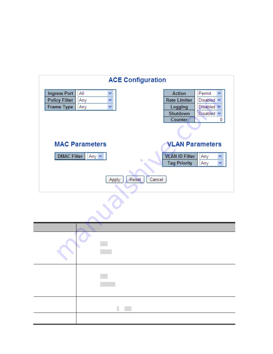
here. The ACE Configuration screen in
Figure 4-10-3
appears.
Figure 4-10-3:
ACE Configuration Page Screenshot
The Page includes the following fields:
Object
Description
Ingress Port
Select the ingress port for which this ACE applies.
■
Any
: The ACE applies to any port.
■
Port n
: The ACE applies to this port number, where n is the number of the
switch port.
Policy Filter
Specify the policy number filter for this ACE.
■
Any
: No policy filter is specified. (policy filter status is "don't-care".)
■
Specific
: If you want to filter a specific policy with this ACE, choose this
value. Two field for entering an policy value and bitmask appears.
Policy Value
When "Specific" is selected for the policy filter, you can enter a specific policy value.
The allowed range is
0
to
255
.
Policy Bitmask
When "Specific" is selected for the policy filter, you can enter a specific policy bitmask.
Summary of Contents for NS4702-24P-4S-4X
Page 1: ...NS4702 24P 4S 4X User Manual P N 1072829 REV 00 01 ISS 14JUL14 ...
Page 23: ...23 Storage Temperature 10 70 degrees C Relative Humidity 5 95 non condensing ...
Page 164: ...164 Figure 4 8 2 Multicast Flooding ...
Page 183: ...183 Figure 4 8 14 IGMP Snooping VLAN Configuration Page Screenshot ...
Page 189: ...189 Figure 4 8 17 MLD Snooping Groups Information Page Screenshot ...
Page 208: ...208 Figure 4 9 6 QoS Egress Port Tag Remarking Page Screenshot ...
Page 218: ...218 Deletes the QCE The lowest plus sign adds a new entry at the bottom of the list of QCL ...
Page 229: ...229 Figure 4 9 18 Voice VLAN Configuration Page Screenshot ...
Page 299: ...299 Figure 4 11 17 Add User Properties Screen Figure 4 11 18 Add User Properties Screen ...
Page 336: ...336 Figure 4 14 2 LLDPMED Configuration Page Screenshot ...
Page 357: ...357 Figure 4 15 4 VeriPHY Cable Diagnostics Page Screenshot ...
Page 367: ...367 ...
Page 391: ...391 ...


