


28
2.2 Installing the Switch
This section describes how to install your Managed Switch and make connections to the Managed Switch. Please read the following
topics and perform the procedures in the order being presented. To install your Managed Switch on a desktop or shelf, simply
complete the following steps.
2.2.1 Desktop Installation
To install the Managed Switch on desktop or shelf, please follow these steps:
Step 1:
Attach the rubber feet to the recessed areas on the bottom of the Managed Switch.
Step 2:
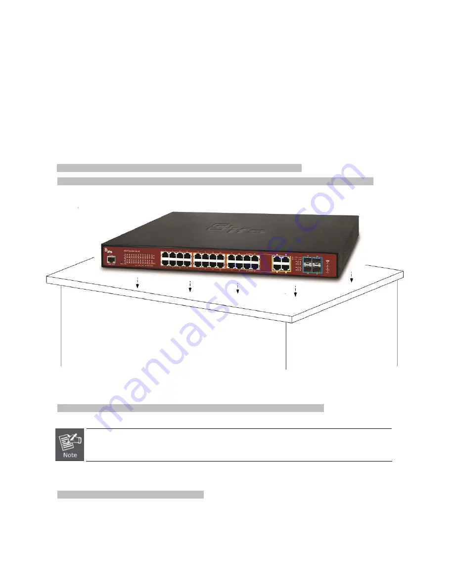
Place the Managed Switch on the desktop or the shelf near an AC power source, as shown in
Figure 2-2-1
.
Figure 2-2-1:
Place the Managed Switch on the Desktop
Step 3:
Keep enough ventilation space between the Managed Switch and the surrounding objects.
When choosing a location, please keep in mind the environmental restrictions discussed in Chapter 1,
Section 4, and specifications.
Step 4:
Connect the Managed Switch to network devices.
Connect one end of a standard network cable to the 10/100/1000 RJ-45 ports on the front of the Managed Switch
.
Connect the other end of the cable to the network devices such as printer server, workstation or router.
Summary of Contents for NS4702-24P-4S-4X
Page 1: ...NS4702 24P 4S 4X User Manual P N 1072829 REV 00 01 ISS 14JUL14 ...
Page 23: ...23 Storage Temperature 10 70 degrees C Relative Humidity 5 95 non condensing ...
Page 164: ...164 Figure 4 8 2 Multicast Flooding ...
Page 183: ...183 Figure 4 8 14 IGMP Snooping VLAN Configuration Page Screenshot ...
Page 189: ...189 Figure 4 8 17 MLD Snooping Groups Information Page Screenshot ...
Page 208: ...208 Figure 4 9 6 QoS Egress Port Tag Remarking Page Screenshot ...
Page 218: ...218 Deletes the QCE The lowest plus sign adds a new entry at the bottom of the list of QCL ...
Page 229: ...229 Figure 4 9 18 Voice VLAN Configuration Page Screenshot ...
Page 299: ...299 Figure 4 11 17 Add User Properties Screen Figure 4 11 18 Add User Properties Screen ...
Page 336: ...336 Figure 4 14 2 LLDPMED Configuration Page Screenshot ...
Page 357: ...357 Figure 4 15 4 VeriPHY Cable Diagnostics Page Screenshot ...
Page 367: ...367 ...
Page 391: ...391 ...


