


29
Connection to the Managed Switch requires UTP Category 5e network cabling with RJ-45 tips. For
more information, please see the Cabling Specification in Appendix A.
Step 5:
Supply power to the Managed Switch.
Connect one end of the power cable to the Managed Switch.
Connect the power plug of the power cable to a standard wall outlet.
When the Managed Switch receives power, the Power LED should remain solid Green.
2.2.2 Rack Mounting
To install the Managed Switch in a 19-inch standard rack, please follow the instructions described below.
Step 1:
Place the Managed Switch on a hard flat surface, with the front panel positioned towards the front side.
Step 2:
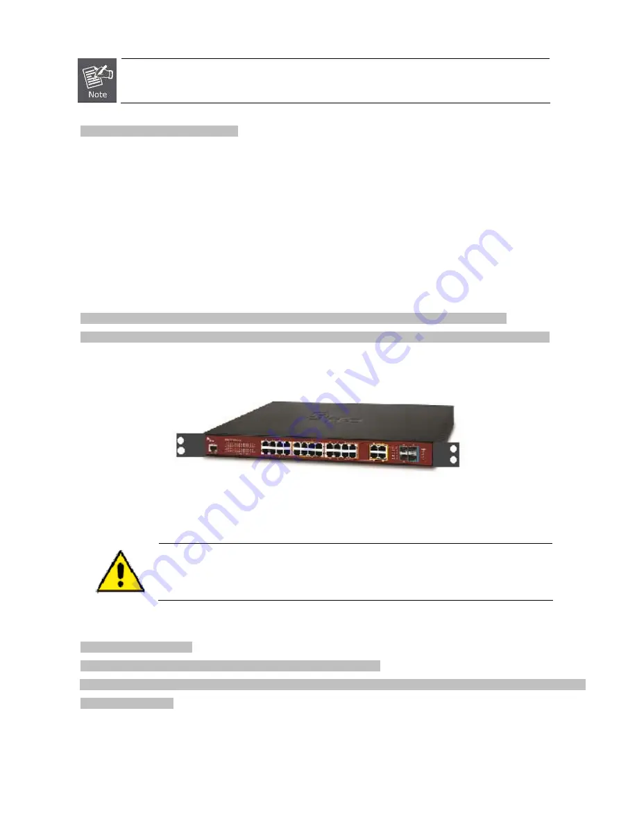
Attach the rack-mount bracket to each side of the Managed Switch with supplied screws attached to the package.
Figure 2-2-2
shows how to attach brackets to one side of the Managed Switch.
Figure 2-2-2:
Attach Brackets to the Managed Switch.
You must use the screws supplied with the mounting brackets. Damage caused to the parts by
using incorrect screws would invalidate the warranty.
Step 3:
Secure the brackets tightly.
Step 4:
Follow the same steps to attach the second bracket to the opposite side.
Step 5:
After the brackets are attached to the Managed Switch, use suitable screws to securely attach the brackets to the rack
, as
shown in
Figure 2-2-3
.
Summary of Contents for NS4702-24P-4S-4X
Page 1: ...NS4702 24P 4S 4X User Manual P N 1072829 REV 00 01 ISS 14JUL14 ...
Page 23: ...23 Storage Temperature 10 70 degrees C Relative Humidity 5 95 non condensing ...
Page 164: ...164 Figure 4 8 2 Multicast Flooding ...
Page 183: ...183 Figure 4 8 14 IGMP Snooping VLAN Configuration Page Screenshot ...
Page 189: ...189 Figure 4 8 17 MLD Snooping Groups Information Page Screenshot ...
Page 208: ...208 Figure 4 9 6 QoS Egress Port Tag Remarking Page Screenshot ...
Page 218: ...218 Deletes the QCE The lowest plus sign adds a new entry at the bottom of the list of QCL ...
Page 229: ...229 Figure 4 9 18 Voice VLAN Configuration Page Screenshot ...
Page 299: ...299 Figure 4 11 17 Add User Properties Screen Figure 4 11 18 Add User Properties Screen ...
Page 336: ...336 Figure 4 14 2 LLDPMED Configuration Page Screenshot ...
Page 357: ...357 Figure 4 15 4 VeriPHY Cable Diagnostics Page Screenshot ...
Page 367: ...367 ...
Page 391: ...391 ...


