36
SRKA4/ISP4400 Server System Product Guide
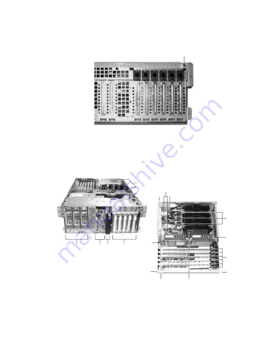
The top cover is held in place by two thumbscrews, each located at the top rear corner of the
chassis. One of two thumbscrews is noted by "A" in Figure 15.
OM09935
A
Figure 15. One of Two Thumbscrews Securing Top Cover
A bezel snaps on to the front of the chassis and allows adequate airflow to cool the system
components. The door in the bezel provides user access to hard drives and the peripheral bay.
Access to the power supplies is provided by removing the front bezel completely. Figure 16 gives
an overhead view of the system with the top cover and front bezel removed.
OM09946
A1
A2
C
B
D
E
E3
E5
E2
E4
E7
E6
E1
G
H
F
I
Figure 16. SRKA4 MP Server
System Without Covers and Bezel
Figure 16a. Overhead View of System
and E-Bay
Summary of Contents for ISP4400 - Server Platform - 0 MB RAM
Page 1: ...SRKA4 ISP4400 Server System Product Guide Order Number A07928 003...
Page 8: ...viii SRKA4 ISP4400 Server System Product Guide...
Page 10: ...10 SRKA4 ISP4400 Server System Product Guide...
Page 20: ...20 SRKA4 ISP4400 Server System Product Guide...
Page 22: ...22 SRKA4 ISP4400 Server System Product Guide...
Page 24: ...24 SRKA4 ISP4400 Server System Product Guide...
Page 34: ...34 SRKA4 ISP4400 Server System Product Guide...
Page 48: ...48 SRKA4 ISP4400 Server System Product Guide...
Page 70: ...70 SRKA4 ISP4400 Server System Product Guide...
Page 78: ...78 SRKA4 ISP4400 Server System Product Guide...
Page 110: ...110 SRKA4 ISP4400 Server System Product Guide...
Page 114: ...114 SRKA4 ISP4400 Server System Product Guide...


