background image

INSYS Modem 56k small EU 2.1 

Installation 


19 


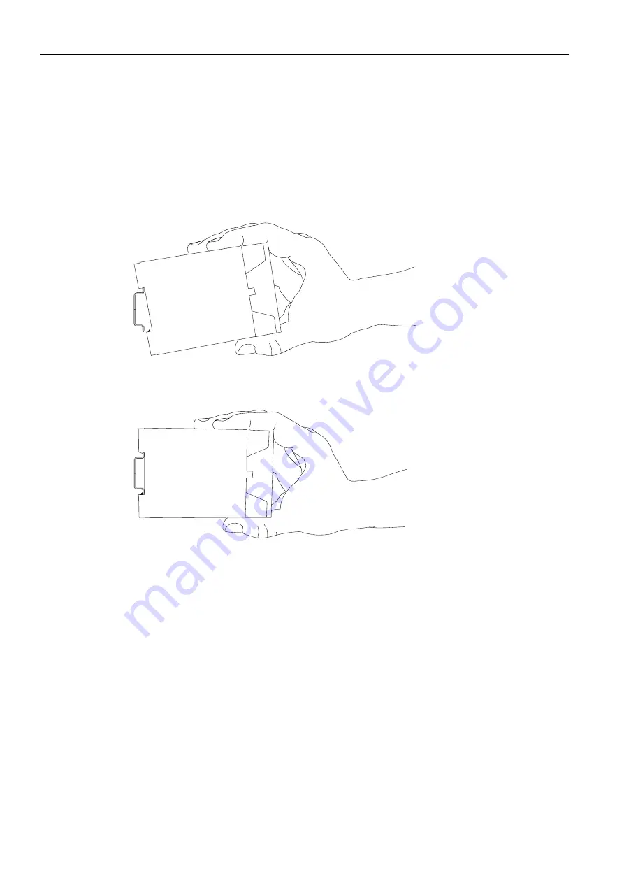
Mount the device to the DIN rail 


Instructions on how to mount the INSYS Modem 56k small EU 2.1 to a DIN 
rail. 

1.


Position the device at the DIN rail as seen in the following diagram. There 
are two snap-in hooks at the outer edge of the DIN rail groove of the INSYS 
Modem 56k small EU 2.1. Hook them into place behind the upper edge of 
the DIN rail when connecting the device. 


2.


Lift the INSYS Modem 56k small EU 2.1 perpendicular to the DIN rail until the 
plastic spring of the third, flexible snap-in hook engages in the DIN rail. 


The INSYS Modem 56k small EU 2.1 is now completely mounted. 


Connecting the power supply 


The device has already been mounted to the DIN rail. 


The power supply is connected and switched off. 

1.


Connect the ground lead of the power supply to the terminal "GND". 

2.


Connect the plus pole of the power supply to the terminal for the power 
supply. 

Summary of Contents for 56k small EU 2.1

Page 1: ...Manual INSYS Modem 56k small EU 2 1 Sep 09...

Page 2: ......

Page 3: ...trademark of Microcom Inc IBM PC AT XT are registered trademarks of International Business Machine Corporation INSYS is a registered trademark of INSYS MICROELECTRONICS GmbH Windows is a registered tr...

Page 4: ...itial Operation 22 11 Operating Principle 24 11 1 Operation with the Terminal Program 24 11 2 Operation with HSComm 25 11 3 User Interface of the Software HSComm Modem 26 12 Functions 28 12 1 Establis...

Page 5: ...rchasing of Legacy Systems 43 15 AT Command Reference 44 15 1 AT Command Overview 45 15 2 AT Messages 61 16 S Registry 64 16 1 Overview S Registry 65 16 2 Description S Registry 66 17 Tables and Diagr...

Page 6: ...ice which may have been in contact with moisture Danger Overvoltage Fire hazard The modem must be secured with a suitable fuse against overvoltage Danger Overcurrent Fire hazard The modem must be secu...

Page 7: ...amage due to chemicals Ketones and chlorinated hydrocarbons dissolve the plas tic housing and damage the surface of the device Never let the device come into contact with ketones e g acetone or chlori...

Page 8: ...6k small EU 2 1 includes all accessories listed below Please check if all accessories are included in the box If a part is missing or dam aged please contact your distributor INSYS Modem 56k small EU...

Page 9: ...he machine directive 2006 42 EC Usage as data transmission device for a PLC The INSYS Modem 56k small EU 2 1 must not be used for the following purposes and used or operated under the following condit...

Page 10: ...V DC Power input sleep 2 4 W Power input connection 2 6 W Weight 100 g Dimensions Width x Depth x Height 23 mm x 110 mm x 75 mm Temperature range 0 C 55 C Maximum allowed humidity 95 non condensing Ta...

Page 11: ...U 2 1 Technical Data 11 4 3 Certifications The INSYS Modem 56k small EU 2 1 has been developed according to the following guidelines and standards R TTE 1999 5 EC DIN EN 55022 Class B DIN EN 61000 6 2...

Page 12: ...EDs on the front panel of the device 5 1 Meaning of the Displays Description Display Meaning Power RX TX LED LED on green Supply voltage available LED off No supply voltage LED blinking orange Data is...

Page 13: ...rface RS232 jack 2 Phone connection RJ12 line jack Table 1 Description of the connections on the front panel of the device 6 2 Terminal Connections on the Top Figure 2 Connections on the top of the de...

Page 14: ...in sub D jack at the device Pin Signal Description 1 DCD Data Carrier Detect 2 RXD Receive Data 3 TXD Transmit Data 4 DTR Data Terminal Ready 5 GND Ground 6 DSR Data set ready 7 RTS Request to send 8...

Page 15: ...ack Pin Signal Description 1 E Not connected GND 2 a2 To connect a phone in series 3 a1 Incoming phone line e g PSTN or PBX 4 b1 Incoming phone line e g PSTN or PBX 5 b2 To connect a phone in series 6...

Page 16: ...g any effect on the transmission format of the data Hardware and software data flow control The INSYS Modem 56k small EU 2 1 can transmit to the application via the control lines of the serial interfa...

Page 17: ...for you or not An arrow will indicate prerequisites which must be fulfilled to be able to process the subsequent steps in a meaningful way You will also learn which software or which equipment you wil...

Page 18: ...ck hazard when touched The INSYS Modem 56k small EU 2 1 may not be used in wet or damp environments or in or very close to water Install the device at a dry location protected from water spray Switch...

Page 19: ...behind the upper edge of the DIN rail when connecting the device 2 Lift the INSYS Modem 56k small EU 2 1 perpendicular to the DIN rail until the plastic spring of the third flexible snap in hook engag...

Page 20: ...witched off accidentally All cables at the INSYS Modem 56k small EU 2 1 are disconnected Danger Exposed electrical components Risk of death through electric shock hazard Prior to the installation swit...

Page 21: ...ng of the snap in hook is pulled apart 3 While you hold the plastic spring of the snap in hook stretched apart pull the INSYS Modem 56k small EU 2 1 away from the DIN rail 4 Unhook the INSYS Modem 56k...

Page 22: ...ten the connection screws 2 Connect the 9 pin serial cable to a free serial interface of your PC Note or remember to which interface COM1 or COM2 you connected the INSYS Modem 56k small EU 2 1 at the...

Page 23: ...If the RX TX LED at the INSYS Modem 56k small EU 2 1 does not light up while you type AT and receive an OK the reason may be that you are con nected to another modem e g with the modem integrated in t...

Page 24: ...6 teraterm html Configuration of the INSYS Modem 56k small EU 2 1 with a terminal program How to configure and operate the INSYS Modem 56k small EU 2 1 with a terminal program The INSYS Modem 56k smal...

Page 25: ...MICROELECTRONICS homepage www insys tec de Configuration and settings of the INSYS Modem 56k small EU 2 1 with HSComm How to configure the INSYS Modem 56k small EU 2 1 with the software HSComm The IN...

Page 26: ...5 Click OK in the status message 11 3 User Interface of the Software HSComm Modem In the following the user interface of the software is displayed These illustrations should help you find the differen...

Page 27: ...gs for dial tone recognition and connection acceptance 16 Not available for INSYS Modem 56k small EU 2 1 17 Button to read the settings from the INSYS Modem 56k small EU 2 1 18 Button to reset the INS...

Page 28: ...in the same way For this the application or the PC with the terminal program at the serial interface must have DTR signalling enabled otherwise the INSYS Modem 56k small EU 2 1 does not accept the in...

Page 29: ...e a dial tone after pick ing up before dialling it indicates NO DIALTONE If the INSYS Modem 56k small EU 2 1 is connected to a telephone system it may be possible that no dial tone but a different aco...

Page 30: ...ber of ring tones after which the INSYS Mo dem 56k small EU 2 1 answers and accepts the connection use the command Replace n with the number of ring tones ATS0 n In order to terminate a connection and...

Page 31: ...ntly established serial connection The function is active as default Configuration with HSComm A configuration using HSComm is not possible because the automatic baud rate detection will re adjust the...

Page 32: ...Mo dem 56k small EU 2 1 will automatically try to determine the optimum connection pa rameters The function is active as default Configuration with HSComm A direct configuration with the HSComm is not...

Page 33: ...T commands To deactivate the error correction as well as the buffer in the INSYS Modem 56k small EU 2 1 for applications with special data format use the command AT N1 To deactivate only the error cor...

Page 34: ...fer is emptied sufficiently for the INSYS Mo dem 56k small EU 2 1 to be able to receive data again the CTS line is set to high Re versely the application can also indicate to the INSYS Modem 56k small...

Page 35: ...o the modem again Analogously the application can insert XON XOFF characters into the data stream to switch the data flow on and off The XON XOFF data flow control is only available when the transmitt...

Page 36: ...he modem identify if the partner is a V 42 modem a MNP modem or a modem without error correction The modem can then autonomously adjust to the partner As default the automatic selection of V 42LAPM or...

Page 37: ...pression AT C3 Configuration with HSComm Direct configuration with the HSComm is not intended The AT command to define a fixed baud rate can be sent to the INSYS Modem 56k small EU 2 1 via the entry f...

Page 38: ...Liechtenstein Norway and Iceland According to the regulations of the TBR 21 a dial up is blocked for 2 hours after 12 un successful dial up attempts In this case the modem indicates the message BLACK...

Page 39: ...d the factory default settings into the INSYS Modem 56k small EU 2 1 use the command AT F In order to load user profile 0 into the INSYS Modem 56k small EU 2 1 use the command ATZ ATZ0 In order to loa...

Page 40: ...EU 2 1 click the button Reset modem page 26 Figure 5 position 18 To reset the INSYS Modem 56k small EU 2 1 to the Factory defaults click the button Reset modem page 26 Figure 5 position 19 Configurati...

Page 41: ...ads e g TeraTerm Firmware update with a terminal program How to load new firmware to the INSYS Modem 56k small EU 2 1 You will need a terminal program that supports ASCII file transfers such as TeraTe...

Page 42: ...e with the firmware loader such as P9 02 16 S37 The upload progress is displayed by dots in the terminal window The INSYS Modem 56k small EU 2 1 will report the successful upload of the firmware loade...

Page 43: ...WEEE guidelines the repurchasing and recycling of legacy systems for our clients is regulated as follows Please send those legacy systems to the following address carriage prepaid Frankenberg Metalle...

Page 44: ...ke on the values 0 to 3 thus e g ATL2 medium volume The modem uses always the parameter 0 for commands which expect a pa rameter but are specified without a parameter The commands ATZ and ATZ0 for ex...

Page 45: ...n protocol without considering a parameter specification If no connection is established or if a fax connection is active an error message is dis played AT B1 1 10 second break signal AT B2 2 10 secon...

Page 46: ...a data modem in the mode AT FCLASS 0 It attempts to connect to another data modem This attempt is re peated until the waiting period that was specified in the S7 registry has expired If this time is e...

Page 47: ...received during the waiting period a connection is established Dial tone delay The INSYS Modem 56k small EU 2 1 performs a dial tone delay before it executes the next character of the parameter strin...

Page 48: ...via 12345 only after hearing the dialling tone Waiting for the dialling tone may be omitted In this case the dialling command is ATX3D012345 AT D n DTR CT108 2 Behaviour DTR CT108 2 behaviour Monitor...

Page 49: ...ult settings AT F0 AT F1 AT GCI Configuring the country code The command AT GCI allows the customization of the modem for different countries By default the modem is configured to Europe CTR21 with AT...

Page 50: ...ration default is RTS CTS AT K0 No data flow control AT K3 Select data flow control RTS CTS default AT K4 Select data flow control XON XOFF AT K5 Select transparent data flow control XON XOFF AT K6 Se...

Page 51: ...nds break immediately to the other modem AT K3 Like AT K2 AT K4 INSYS Modem 56k small EU 2 1 inserts a break into the data transmit ted to the other modem AT K5 Like AT K4 Return from the online comma...

Page 52: ...TM2 Speaker always ON ATM3 Speaker ON during connection setup AT MR n Displaying the modulation type The command AT MR n enables the display of the modulation type after the mes sage CONNECT AT MR 0 S...

Page 53: ...V92 Model 336 V34 Parameter Modulation The modulation parameter determines the preferred automode 1 or the mandatory automode 0 modulation type The following values are available V21 V 21 300 V22 V 2...

Page 54: ...The optional parameter maxbaud determines the highest possible baud rate the INSYS Modem 56k small EU 2 1 sends with AT N n Selecting the error correction This command determines which type of error c...

Page 55: ...a fall back or retrain is triggered if the line quality is too bad to enable a new negotiation of the connection if necessary with a slower speed High values indicate bad quality These values are con...

Page 56: ...oltage Use the command AT TRV to measure the phone line voltage Tip Ring Voltage The result is yielded in volt For an existing connection the voltage range is 5 V 12 V Oth erwise the voltage is higher...

Page 57: ...fall forward fall back or retrain occurred during the connection To impact the negotiated data rate use the command AT MS PROTOCOL Displays the used error correction protocol LAPM equals a V 42 secur...

Page 58: ...this func tion The following countries support CLIP Australia Belgium China Denmark Germany Finland Great Britain Hong Kong India Ireland Iceland Italy Canada Korea New Zealand The Netherlands Norway...

Page 59: ...the mes sage NO CARRIER is displayed The message is displayed without speci fying the speed ATX1 Like ATX0 but CONNECT message with speed information ATX2 Dialling tone detection is active i e a dial...

Page 60: ...user default 1 is loaded AT Z n Saving telephone numbers The command saves four entries permanently in the EEPROM Each entry may consist of up to 35 characters The entries may be overwritten and must...

Page 61: ...X X X X 12 CONNECT 9600 1 X X X X 13 CONNECT 7200 1 X X X X 14 CONNECT 12000 1 X X X X 15 CONNECT 14400 1 X X X X 16 CONNECT 19200 1 X X X X 17 CONNECT 38400 1 X X X X 18 CONNECT 57600 1 X X X X 19 CO...

Page 62: ...X X X X X 79 CARRIER 33600 X X X X X 80 PROTOCOL ALT X X X X X 81 PROTOCOL ALT CELLULAR X X X X X 84 CONNECT 33600 X X X X X 91 CONNECT 31200 X X X X X 150 CARRIER 32000 X X X X X 151 CARRIER 34000 X...

Page 63: ...RRIER 38667 X X X X X 187 CARRIER 41333 X X X X X 188 CARRIER 42667 X X X X X 189 CARRIER 45333 X X X X X 190 CARRIER 46667 X X X X X 191 CARRIER 49333 X X X X X 192 CARRIER 50667 X X X X X 193 CARRIE...

Page 64: ...only be read others only al low to enter a particular range of values If the range of values is exceeded the modem will report OK although the value was not accepted We therefore recommend to immediat...

Page 65: ...14 254 14 S12 Transmission clock of the ESC characters 0 02 s 0 255 50 S14 General settings 138 S21 Settings for V24 52 S22 Settings 117 S24 Time period until switching into sleep mode s 0 255 0 S25 T...

Page 66: ...character S5 Backspace character Backspace character S6 Waiting period for dial tone Maximum waiting time for the dialling tone After the modem went off hook it waits 7 seconds for the dialling tone...

Page 67: ...carrier signal and hang up The time which leads to termination after carrier frequency loss In S10 the time period for which the modem waits for the disconnection if it can no longer detect the carrie...

Page 68: ...ATL3 Bit 2 3 Speaker control Speaker control 0 Off ATM0 1 On until carrier ATM1 2 Always on ATM2 3 On at establishing Bit 4 6 Error message group Limit result codes 0 like ATX0 4 like ATX1 5 like ATX2...

Page 69: ...elect 0 CCITT modulation 1 Bell modulation Bit 7 Reserved Reserved S29 Time period for modifier flash Sets the time period in tenths of seconds after which the modem hangs up due to a flash in the dia...

Page 70: ...MNP connec tion In case of failure a direct mode connection is established 6 Reserved 7 Modem attempts to establish an MNP connec tion In case of failure a normal mode connec tion is established Bit 3...

Page 71: ...ion type retrain Bit Meaning Bit 0 1 Select compression type Compression selection 0 No compression AT C0 1 MNP5 AT C1 2 V 42bis AT C2 3 MNP5 or V 42bis AT C3 Bit 2 Auto retrain Auto retrain control 0...

Page 72: ...y more ten attempts S86 14 Protocol error S86 15 DTR drop S86 16 Remote terminal demanded cleardown GSTN cleardown S86 17 Inactivity timer expired S86 18 Desired speed is not supported S86 19 Long spa...

Page 73: ...CONNECT message with line speed Bit 1 CONNECT ARO message for error corrected connection Bit 2 CARRIER messages enabled messages 40 47 Bit 3 PROTOCOL messages enabled messages 70 80 Bit 4 Reserved Bi...

Page 74: ...e sub D jack 14 Table 5 Layout description of the RJ12 and TAE plugs 15 Table 6 Description of the functions on the HSComm tab Modem 27 Table 7 AT responses depending on the ATX command 63 Table 8 Ove...

Page 75: ...7 67 Dial tone detection 59 Dialling 46 DSR behaviour 56 DTR 48 68 69 DTR signalling 28 Echo 49 Energy conservation mode 68 Error 54 Error correction 16 58 Error correction protocols 16 Error event co...

Page 76: ...Sleep mode 68 Software reset 60 Speaker 51 52 Standards 11 Symbols 17 Telephone connection quality 55 Telephone system 29 Terminal program 24 28 41 Terminating 49 Tone dialling 28 Tone dialling metho...

Page 77: ......

Reviews: