


Chapter 2: Getting started
TT 98-123789-D
18
Detaching the antenna
Grab the antenna near one of the magnets and lift it. When one magnet is loose, the other two are
easy to “break off”. In some situations the magnetic force may be so great that it is necessary to
unscrew the antenna first and remove the magnets separately.
Connecting cables
After inserting the SIM card and mounting the EXPLORER 527 and antenna, connect all relevant
cables.
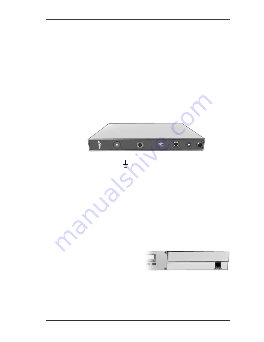
Connector panel
The connector panel is placed on the rear side of the EXPLORER 527 and has the following
connectors:
•
Threaded GND stud, marked
•
USB connector for service use, marked
USB
•
Phone/Fax connector for phone, fax or analog modem, marked
Phone/Fax
•
Antenna connector, marked
Antenna
•
LAN connector for data equipment, marked
LAN
•
DC power connector for connection to 12/24 V DC in a car, marked
DC
For information on how to connect to a specific interface, see the corresponding section in
Chapter 4, Using the interfaces. The end of this section describes how to connect to the antenna
and to power.
Front connector
The EXPLORER 527 has an additional
Phone/Fax connector, marked
Phone/Fax
, in
the front panel of the EXPLORER 527.


