9.0 OPERATING INSTRUCTIONS
TS1A–13A
http://air.irco.com
41
9.7
ALARMS
If a critical value is exceeded (during any mode of operation), an alarm
sequence will take place. In the sequence, the controller will indicate
the source of the alarm by illuminating the appropriate LED in the
synoptic display. Concurrently, the controller will de–energize both the
compressor motor and fan motor contactors. When in alarm mode, the
“Power ON” status LED, the general alarm LED, and the component
alarm LED will light.
Power is not issued back to the starter until the alarm message has
been reset and the alarm parameters have returned to normal range.
The operator will use the Reset button on the front of the controller to
reset the alarm. Pressing the RESET button twice within a 2 second
period will reset the alarm associated with the lit LED.
The following sections describe each alarm message and the
conditions associated with each.
High Compressor Discharge Pressure Alarm
This alarm occurs when the pressure switch at the discharge of the
compressor in the refrigeration circuit opens. When this switch opens,
the compressor and fan motor contactors should be de–energized.
This alarm will need to be cleared at the Intellisys only after the problem
is corrected.
Low Compressor Suction Pressure Alarm
This alarm occurs when the pressure switch on the suction pipe opens,
likely due to refrigerant leakage and loss. When this switch opens, the
compressor and fan motor contactor should be de–energised. This
alarm will need to be cleared at the switch, then the Intellisys, only after
the problem is corrected.
High Compressor Discharge Temperature Alarm
This alarm occurs when the temperature switch at the discharge of the
compressor in the refrigeration circuit opens. When this switch opens,
the compressor and fan motor contactors should be de–energized.
Compressor Motor Overload
This alarm occurs when the auxiliary contact in the compressor motor
overload is opened. When this alarm is active, the compressor and fan
motor contactors should be de–energized. The general alarm LED
should be energized. No other LED on the synoptic display will be
energized to show the source of this fault.
2AT Sensor failure
This alarm occurs when 2AT evaporator temperature sensor fails in an
open/short circuit condition. The general alarm, Low Evaporator, and
High Evaporator LED’s should be illuminated.
Remote Alarm Signal
The Intellisys controller has dry contact (volt–free) outputs to allow the
user to receive an alarm signal to a remote location. The signal may be
connected at the Intellisys as either normally open or normally closed.
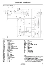
See the dryer electrical schematic for more information (block A in
CON).
Drain Valve Alarm (Optional)
When the factory or aftermarket electric no–loss drain valve is
equipped and properly installed, any alarm signals sent to the Intellisys
will be displayed. The fault must be corrected and cleared at the drain
valve first, then at the Intellisys controller.
Summary of Contents for TS10A
Page 2: ......
Page 10: ...5 0 SAFETY TS1A 13A http air irco com 8 5 3 TEXT DECALS NORTH AMERICA ...
Page 50: ......
Page 52: ......
Page 60: ...5 0 SECURITE TS1A 13A http air irco com 8 5 3 DÉCALCOMANIES DES TEXTES AMÉRIQUE DU NORD ...
Page 101: ......
Page 102: ......
Page 104: ......
Page 112: ...5 0 SEGURANÇA TS1A 13A http air irco com 8 5 3 AUTOCOLANTES DE TEXTO AMÉRICA DO NORTE ...
Page 152: ......
Page 161: ...5 0 SEGURIDAD TS1A 13A http air irco com 8 5 3 CALCOMANÍAS DE TEXTO AMÉRICA DEL NORTE ...
Page 203: ......
Page 204: ......

