4
Form MHD56406 Edition 2
OPERATION
It is recommended that the user and owner check all appropriate and applicable
regulations before placing this product into use. Refer to Product Safety Information
Manual.
The hoist operator must be carefully instructed in his or her duties and must
understand the operation of the hoist, including a study of the manufacturers
literature. The operator must thoroughly understand proper methods of hitching
loads and should have a good attitude regarding safety. It is the operators
responsibility to refuse to operate the hoist under unsafe conditions.
WARNING
• The hoist is not designed or suitable for lifting, lowering or moving people.
• Never lift loads over people.
• The hook latch is intended to retain loose slings or devices under slack
conditions. Use caution to prevent the latch from supporting any of the load.
Hoist Controls
Pendant Operation
Refer to Dwg. MHP3111 on page 6,
A.
Lower;
B.
Raise.
The pendant is a control that allows the operator to control the positioning of a
load. The two-lever pendant will control hoist movement in the “UP” and “DOWN”
direction. Always apply smooth even pressure to pendant levers, avoid quick starts
and abrupt stops. This will allow smoother control of suspended loads and reduce
undue stress on components.
Emergency Stop
Refer to Dwg. MHP3112 on page 6,
A.
Lower;
B.
Raise;
C.
Emergency Stop.
INSPECTION
Inspection information is based in part on American Society of Mechanical Engineers
Safety Codes (ASME B30.16).
WARNING
• All new, altered or modified equipment should be inspected and tested by
Ingersoll Rand Certified Service Technicians to ensure safe operation at rated
specifications before placing equipment in service.
• Never use a hoist that inspection indicates is damaged.
Frequent and periodic inspections should be performed on equipment in regular
service. Frequent inspections are visual examinations performed by operators or
personnel trained in safety and operation of this equipment and include observations
made during routine equipment operation. Refer to Product Maintenance Information
Manual for Periodic inspections which are thorough inspections conducted by
Ingersoll Rand
Certified Service Technicians.
ASME B30.16 states inspection intervals depend upon the nature of the critical
components of the equipment and the severity of usage. The inspection intervals
recommended in this manual are based on intermittent operation of the hoist eight
hours each day, five days per week, in an environment relatively free of dust,
moisture, and corrosive fumes. If the hoist is operated almost continuously or more
than the eight hours each day, more frequent inspections will be required.
Careful inspection on a regular basis will reveal potentially dangerous conditions
while still in the early stages, allowing corrective action to be taken before the
condition becomes dangerous.
Deficiencies revealed through inspection, or noted during operation, must be
reported to a
Ingersoll Rand
Certified Service Technician. A determination as to
whether a condition constitutes a safety hazard must be decided, and the correction
of noted safety hazards accomplished and documented by written report before
placing the equipment in service.
Frequent Inspection
On equipment in continuous service, frequent inspections should be made by
operators at the beginning of each shift. In addition, visual inspections should be
conducted during regular service for any damage or evidence of malfunction.
1.
Hoist.
Check for visual signs or abnormal noises (grinding, etc.) which could
indicate a potential problem. Make sure all controls function properly and return
to neutral when released. Check chain feed through hoist and bottom block. If
chain binds, jumps, is excessively noisy or “clicks,” clean and lubricate chain. If
problem persists, replace chain. Do not operate hoist until all problems have
been corrected.
2.
Hooks.
Check for wear or damage, increased throat width, bent shank or twisting
of hook. Replace hooks which exceed the throat opening discard width specified
in Table 3 on page 4 or which exceed a 10° twist. Refer to Dwg. MHP0040 on
page 6,
A.
Throat Width; and refer to Dwg. MHP0111 on page 6,
A
. Twisted DO
NOT USE;
B.
Normal Can Be Used. If hook latch snaps past tip of hook, the hook
is sprung and must be replaced. Refer to the latest edition of ASME B30.10
“HOOKS” for additional information. Check hook support bearings for lubrication
or damage. Ensure that they swivel easily and smoothly.
3.
Hook Latch.
Make sure hook latch is present and operating. Replace if necessary.
4.
Air System.
Visually inspect all connections, fittings, hoses and components for
indication of air leaks. Repair any air leaks found. Check and clean filter.
5.
Emergency Stop.
Check Emergency Stop for proper operation.
6.
Limit Switch Devices.
Without a load on the hook, the load block should be
inched into the limit switch (run at slow speed), and the function of the limit
switch, to stop the load, should be confirmed. Similarly, this should be
performed for full extension of the chain.
7.
Brake System.
Check braking system for proper operation.
8.
Load Chain.
Examine each of the links for bending, cracks in weld areas or
shoulders, traverse nicks and gouges, weld splatter, corrosion pits, striation
(minute parallel lines) and chain wear, including bearing surfaces between chain
links. Refer to Dwg. MHP0102 on page 6,
A.
Diameter;
B.
Welded Area;
C.
Wear in
these areas. Replace a chain that fails any of the inspections. Check chain
lubrication and lubricate if necessary. Refer to ‘Load Chain’ in “LUBRICATION”
section on page 5.
NOTICE
• The full extent of load chain wear cannot be determined by visual
inspection. At any indication of load chain wear, inspect the chain and chain
wheel in accordance with instructions in “Periodic Inspection.” Refer to Product
Maintenance Information Manual.
9.
Load Chain Reeving.
Ensure welds on standing links are away from load sheave.
Reinstall chain if necessary. Make sure chain is not capsized, twisted or kinked.
Adjust as required. Refer to Dwg. MHP0043 on page 6,
A.
Make certain bottom
block has NOT been flipped through the chain falls.
10.
Labels and Tags.
Check for presence and legibility. Replace if necessary.
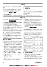
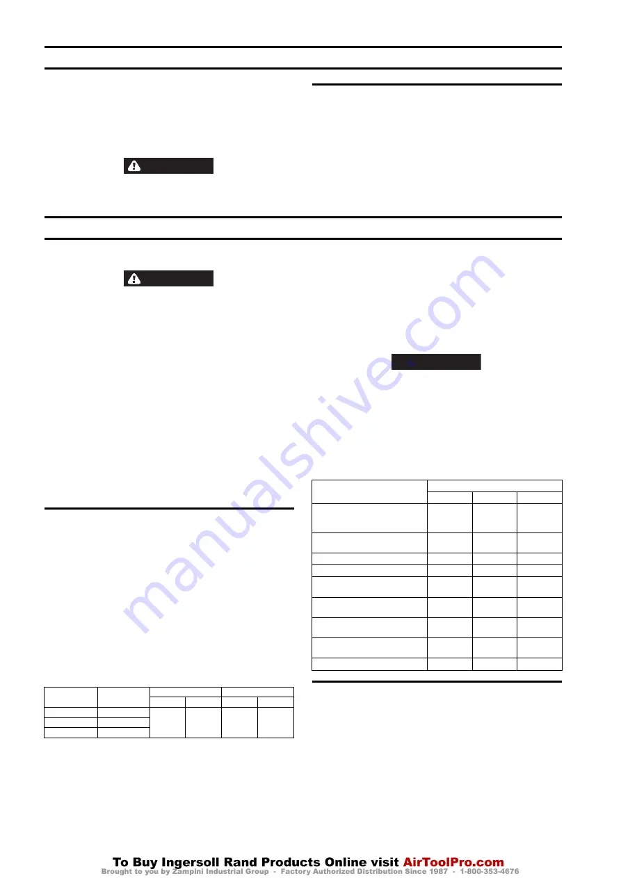
Table 4: Frequent Inspection Interval:
Hoists Not in Regular Use
1. Equipment which has been idle for a period of one month or more, but less than
six months, shall be given an inspection conforming to the requirements of
‘Frequent Inspection’ before being placed in service.
2. Equipment which has been idle for a period of over six months shall be given a
complete inspection conforming with the requirements of ‘Periodic Inspection’
before being placed in service. Refer to Product Maintenance Information
Manual.
3. Standby equipment shall be inspected at least semiannually in accordance with
the requirements of ‘Frequent Inspection’.
Table 3: Hook Throat Normal and Discarded Width
Hoist
Model
Capacity
(tonne)
Throat Width *
Discard Width *
in.
mm
in.
mm
CL125K
1/8
0.945
24
1.042
27.6
CL250K
1/4
CL500K
1/2
* Dimensions are with no latch installed.
Item
Conditions
Normal
Heavy
Severe
All functional operating mechanisms
for maladjustment and unusual
sounds.
Monthly
Weekly
Daily
Hoist Braking System for proper
operation.
Monthly
Weekly
Daily
Hooks, per guidance given in manual.
Monthly
Weekly
Daily
Hook Latch for proper function.
Monthly
Weekly
Daily
Load Chain, per guidance given in
manual.
Monthly
Weekly
Daily
Load Chain reeving for compliance to
manufacturers recommendations.
Monthly
Weekly
Daily
Air System; lines, valves, and other
parts for leakage.
Monthly
Weekly
Daily
Pendant and e-stop; confirm proper
operation.
Monthly
Weekly
Daily
Limit Switches.
Monthly
Weekly
Daily
Summary of Contents for CL125K
Page 96: ...www ingersollrandproducts com...


