


45
If breaker is Rated in MVA, and is being
Applied at Voltage other than Nameplate:
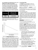
There are occasions when the breaker is rated in MVA
at a given voltage, and the breaker is being applied at a
different voltage. No kA value is available. To calculate kA
maximum rated symmetrical fault current from MVA, use
the equation
I
L
= S
3
/
√
3 (V
LL
) to derive single phase
current, where
I
L
is the individual phase current in kA, S
3
is the three phase power in MVA, and V
LL
is the line-to-line
voltage in kV.
Example:
Given:
Breaker is rated at 38kV, 1,200 MVA
interrupting duty.
Breaker is to be applied at 34kV.
Calculate:
IL = S3
/ √3 (VLL),
IL = 1,200 MVA / 34kV √3
IL = 20.401kA, or approximately 20kA
Danger Limit = (NF ) I
2
x T
Danger Limit = (100) (20kA)
2
(0.024s)
Danger Limit = 9,600,000,000 A
2
s
Danger Limit = 9.6 x 10
9
A
2
s
Program:
Contact Life Danger Limit = “9.6e9”
Contact Life Warning Limit
The Contact Life Warning Limit is the warning setpoint for
cumulative
I
x T
or
I
2
T
duty. The intent of this setpoint is
to allow the generation of a warning alarm prior to ultimate
contact wear (Danger Limit). Accordingly, when used in this
mode it is set at a fraction of the Danger Limit setpoint.
Note:
When the
OPTI
mizer
2
is cold-started, the Warning
Limit parameter is set to ZERO, which disables this
alarm.
Set at an Arbitrary Percentage of the Danger Limit
To set the WARNING setpoint at an arbitrary percentage of
the DANGER setpoint simply use the WARNING command
followed by the percentage value.
Example:
Given:
Breaker Danger Limit setpoint has been determined
to be (6.4) 10
6
A
2
S.
To set the Warning Limit to 30% of the Danger
limit…
Program:
Contact Life Warning Limit(%) = “30”
The
OPTI
mizer
2
will automatically
calculate the Warning Limit
I
2
x T
.
Set at One Fault Rated Interruption less than the Danger
Limit
Setting the Warning Limit at one fault interruption operation
allows a Warning alarm to be issued before another
fault takes place and brings the breaker cumulative
I
2
x T
to the Danger Limit. Use the equation Warning Limit =
1 / N
F
, where N
F
is the maximum number of fault rated
interruptions.
Example:
Given:
Breaker DANGER setpoint has been determined
to be (6.4) 10
6
A
2
s and it can withstand 15
operations at fault interrupt current
Calculate:
Warning Limit = 1 / N
F
Warning Limit = 1 /15]
Warning Limit = 0.067 or 6.7%, round to 7%
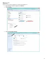
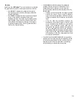
To set the Contact Life Warning Limit, select the
CONFIGURATION tab and click “EDIT”:
Program:
Contact Life Warning Limit(%) = “7”
(The
OPTI
mizer
2
will automatically calculate the Warning
Limit I
2
x T.)
There is no guidance from standards on the following
issues, so Alarm Limit selection is for the applying
company to decide.
The correct Administrator’s password is needed for these
settings to be saved.
Trip Time Alarm Limit
The
OPTI
mizer
2
will measure the response time
of the trip latch mechanism, if programmed for
Input Modes 2 or 4. A Trip Time Alarm Limit can be
programmed in milliseconds. When the measured
Trip Time reaches or exceeds this Alarm Limit an
alarm will be asserted.
It is recommended that this limit be set for 25% to
35% above the typical trip latch response time to
reduce nuisance alarms.
Note:
When the
OPTI
mizer
2
is cold-started, the Trip
Time Alarm Limit parameter is set to ZERO, which
disables this alarm.
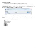
To set the Trip Time Alarm Limit, select the CONFIGURATION
tab and click “EDIT”:
Program:
Trip Time Alarm Limit = “13”


