


43
Use of ANSI / IEEE C37.06-1989, Rating of Power Circuit
Breakers under a Symmetrical Fault Basis
ANSI / IEEE C37.06-1989 can provide guidance for the
time of latch release and the duration of arcs for power
circuit breakers. The latch release time is approximately
the same time value as the main contacts parting, which
is required for the
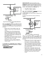
A Input Delay
setting. This standard
addresses power circuit breakers with voltage ratings
from 13 kV to in excess of 500 kV. To be qualified as an
ANSI rated breaker, which most utilities use, the following
performance criteria must be met under symmetrical fault
conditions:
Breaker Voltage
M
UST
c
LeAR
T
IMe
(
TRIp
INITIATe
TO
ARc
exTINgUIShMeNTS
)
<230kV
3 cycles at 60Hz
>230kV
2 cycles at 60Hz
Table 6: Must-Clear Times of Breakers, Voltage Dependent
Note:
Pre-1989 breakers may not conform to this
standard. Always use manufacturers data or oscillographic
data if available.
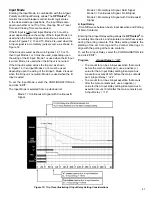
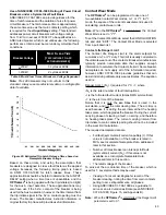
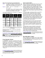
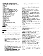
Figure 20: Estimated Trip Latch Release Times based on
Nameplate Breaker Voltage
Based on these limits, and using the assumption that
breakers are designed to clear a fault faster as the applied
voltage increases; the following timing graph is based
on ANSI C37.06-1989 for latch release times. These
approximations should be helpful to determine the A INPUT
DELAY setting when a time trace is unavailable, and the
OPTI
mizer
2
is being applied with the trip initiates (red light)
for the Aux A input assertion. These approximations may
also have use if the 52 / a contact of the breaker is being
used for the Aux A assertion, however, the time interval from
the trip initiate signal to the 52 / a contact opening must be
known. The breaker manufactures instruction literature or
original factory trip trace will provide useful information.
Contact Wear Mode
The
OPTI
mizer
2
can be programmed to use one of
two available Contact Wear modes,
I
x T
or
I
2
T
. In
I
2
T
mode, the square of the current measurement is used in
calculating contact wear units.
Note:
When the
OPTI
mizer
2
is cold-started, the Contact
Wear Mode is set to “
I
2
T
”.
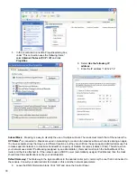
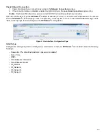
To set the Contact Wear Mode, select the CONFIGURATION
tab and click “EDIT”: The Contact Wear Mode is selected
from a pull-down list.
Contact Life Danger Limit
The Contact Life Danger Limit is the alarm setpoint for
cumulative
I
x T
or
I
2
T
duty. This limit is usually correlated to
the ultimate wear-out of the contacts. Breaker manufacturers
typically provide nameplate data that supplies enough
information to calculate the Contact Life limit. Some breaker
nameplates do not supply all of the information required,
however, ANSI C37.06-1989 provides guidelines that can
assist in deriving ultimate duty wear estimates. The equation
used is:
Danger Limit = (N
F
)
I
(squared for
I
2
T)
•
T
, where
• N
F
is the rated number of fault interruptions,
• I
is the full rated fault current (Amps RMS symmetrical)
• T
is the arc time of the breaker.
Notice that it is only the
arc time
that is used in the
calculation, and not the total clearing time. The arc time is
used because it is during the arc interval that the heating
takes place, which degrades the breaker. During the current
carrying phase of clearing a fault, no arcing, and therefore
no heating takes place. The current carrying interval from
trip initiate to main contacts parting should not be included
in the wear limit calculation.
The required nameplate data are:
• Full fault (symmetrical) current capability (
I
). If this
value is not available, or if the breaker is rated in
MVA, see
Incomplete Nameplate Data
, addressed
later in this section.
• Number of times breaker can interrupt full fault
(symmetrical) current (N
F
). If this value is not
available, see
Incomplete Nameplate Data
,
addressed later in this section.
• The rated voltage of the breaker.
To arrive at the arc duration time of the breaker, which is
used for
T
, several methods may be used:
• Viewing of a recent oscillographic record of the
breaker clearing, noting the time from main contacts
parting to arc extinguishments, all phases.
• Using ANSI / IEEE C37.06-1989 as a guideline to
arrive at an arc duration estimate (see ANSI / IEEE
C37.06-1989, Figure 15, and Appendix B).
Note:
When the
OPTI
mizer
2
is cold-started, the Danger Limit
parameter is set to 0.1.


