


23
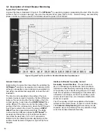
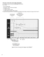
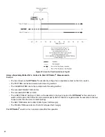
Figure 6B: Event to Time Correlation of Fig 6A,
Using Trip Coil Voltage to Start
OPTI
mizer
2
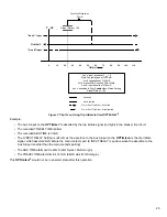
Example:
• The Aux A input on the
OPTI
mizer
2
is asserted by the Trip Signal voltage measured across the Trip Coil.
• The recorded TRIP TIME is 25mS
• The recorded TRAVEL TIME is 51mS (94mS – 43mS)
• The recorded ARC TIME is 32mS
• The recorded CLEARING TIME is 56mS
• The A INPUT DELAY Setting is -19mS, as the assertion to the Aux A input on the
OPTImizer
2
is the breaker Aux A
contact, which opens 19mS after the main contacts part (A INPUT DELAY is negative when the assertion to the Aux
A input is later than the main contacts parting)
• The TRIP TIME alarm limit is 30mS
• The ARC TIME alarm limit is 48mS (32mS plus 16mS margin)
• The CLEARING TIME alarm limit is 78mS (56mS plus 22mS margin)
• The TRAVEL TIME alarm limit is 76mS (51mS plus 25mS margin)
This
OPTI
mizer
2
would not be in an alarm state after this operation.


