


3
Contents
List of Tables ...........................................................................................................................6
1 INTRODUCTION ...........................................................................................................7
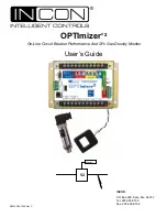
1.1 Overview ..........................................................................................................................7
1.2 Operation Overview ........................................................................................................7
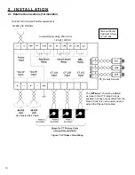
2 INSTALLATION ...........................................................................................................10
2.1 External Connections (Termination) ...............................................................................10
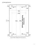
2.2 Mounting Dimensions .................................................................................................... 11
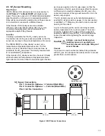
2.3 SF
6
Sensor Mounting .................................................................................................... 13
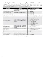
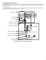
General Planning Considerations................................................................................................ 15
3 APPLICATION GUIDE ................................................................................................17
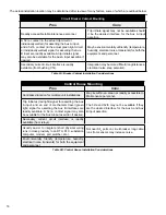
3.1 Breaker Wear Symptoms ...............................................................................................17
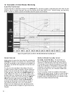
3.2 Description of Circuit Breaker Monitoring ......................................................................18
Interface to the Breaker Control Circuits ..................................................................................... 19
I
2
x T or I x T
Wear Duty ................................................................................................................ 21
Time Line to Trip Trace Correlation (Examples) .......................................................................... 22
Alarm Set-points .......................................................................................................................... 26
3.3 Description of SF6 Density Monitoring .........................................................................28
4 PROGRAMMING .......................................................................................................29
4.1
Initial Communication With the OPTImizer2 ...................................................................29
Configuring IP Properties for Communication ............................................................................. 29
Initial Set-up ................................................................................................................................ 33
4.2 General ..........................................................................................................................35
IP ADDRESS ............................................................................................................................... 35
DATE / TIME ............................................................................................................................... 35
DIAGNOSTICS ............................................................................................................................ 35
DNP3.0 SETTINGS ..................................................................................................................... 35
CIRCUIT BREAKER INFORMATION .......................................................................................... 36
4.3 Circuit Breaker Monitor Settings ....................................................................................36
Input Mode .................................................................................................................................. 41
Contact Wear Mode ................................................................................................................... 43
If breaker is Rated in MVA, and is being Applied at Voltage other than Nameplate: ................... 45
Contact Life Warning Limit ......................................................................................................... 45
Trip Time Alarm Limit ................................................................................................................... 45
Arc Time Alarm Limit ................................................................................................................... 46
Clearing Time Alarm Limit ........................................................................................................... 46
Travel Time Alarm Limit ............................................................................................................... 46
Closing Time Alarm Limit ............................................................................................................. 46
Operations Count Alarm Limit ..................................................................................................... 47
No Operations Alarm Limit .......................................................................................................... 47
Restrike Alarm ............................................................................................................................ 47
4.4 SF
6
MONITOR SETTINGS ............................................................................................49
Low Gas Warning Limit ............................................................................................................... 49
Low Gas Alarm Limit ................................................................................................................... 49
Density or Pressure Trend Limit .................................................................................................. 49
SF
6
Sensor Signals ..................................................................................................................... 50
Analog Sensor - Signal Low (Milliamps) ..................................................................................... 50
Analog Sensor - Signal Low Represents (Units) ......................................................................... 50
Analog Sensor - Signal High (Milliamps) .................................................................................... 50
Analog Sensor - Signal High Represents (Units) ........................................................................ 50
4.5 ACTIONS ........................................................................................................................51
Preset Remaining Contact Life.................................................................................................... 51
Preset Operation Number ........................................................................................................... 52
Clear Latched Alarms .................................................................................................................. 52
Reset Operations Counter........................................................................................................... 52
Reset SF
6
Density Trend Data .................................................................................................... 53


