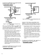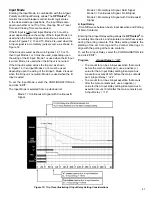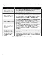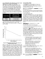
35
4.2 General
IDENTIFICATION
The
OPTI
mizer
2
provides four text fields (ID Line 1
through 4) that can be used to identify the circuit breaker,
substation, etc... Up to 40 text characters of all types can
be entered in each field. (Site Name, Address, City, State
and Telephone are a few suggestions. Any desired text
can be entered). Note that the text entered in ID Line 1 will
be used in the heading of the user interface.
To change the identification text, select the
CONFIGURATION tab and click "EDIT". Type the desired
text in the field.
PASSWORD
The
OPTI
mizer
2
uses three levels of access rights,
Administrator, User and Guest. Each has a separate
password. The Default password for the Administrator is
“admin”.
The Default password for the User is “user”. There is
no default password for the Guest. It is STRONGLY
recommended that the password for the Administrator be
changed immediately. The password for the User should
also be changed for better security.
A password for the Guest can be also added to prevent
access to viewing all data. Passwords are limited to a
maximum of 40 characters. The password can contain
upper and lower case letters and any keyboard character.
If the Administrator’s password is changed and then
forgotten, program settings will not be able to be changed.
If this occurs call the INCON factory for assistance. An
INCON service technician can use a diagnostic password
to reset the Administrator’s password. Remote internet
access to the
OPTI
mizer
2
is required for the technician to
do this.
Guest Level rights
include the ability to VIEW all
Status, Alarms, Configuration and Preferences data, and
download reports from the history page.
User Level rights
include all of the above plus the ability
to clear all alarms, reset the Operations Count and preset
Contact Life.
Administrator Level rights
include all of the above plus
saving changes to passwords and program settings.
IP ADDRESS
The
OPTI
mizer
2
is capable of internet communication. A
web browser can be used to “log on” to the
OPTI
mizer
2
either locally (with the short cable provided) or remotely
through a network and perform all user interface functions.
To access an
OPTI
mizer
2
, its IP address is needed. A
new
OPTI
mizer
2
is shipped with the default IP address of
“
192.12.27.1
” As part of a network, the
OPTI
mizer
2
will
need a different IP address.
To change the IP address, select the
CONFIGURATION tab and click “EDIT”:
Program:
IP Address = “nnn.nnn.nnn.nnn”
To change the passwords, select the
CONFIGURATION tab and click “EDIT”:
Program:
Administrator = “ABCdef123%^&…”
Program:
User = “ABCdefg123%^&…”
Program:
Guest = “ABCdefg123%^&…”
The correct (old) Administrator’s password will need
to be given for the changes to be saved.
DATE / TIME
The date and time are needed for reference on the trip
records and event history logging.
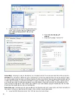
To change the date and time, select the CONFIGURATION
tab and click “EDIT”:
Time Zone:
The local time zone is selected from a pull-
down list.
System Clock:
The clock time and date can be manually
entered using the pull-down
lists or…
Time Server:
The system clock can be set from an NTP
server. The IP address of this server can be entered in the
blank field.
DIAGNOSTICS
The
OPTI
mizer
2
is capable of sending diagnostic
information to an IP address. This is used by INCON
Technical Service to help in troubleshooting. It should
be used only when instructed by an INCON Service
Technician. The Technician will provide the IP address
and further instructions. Always call the INCON Technical
Service Division for assistance when troubleshooting a
problem. This Diagnostics utility may help in finding the
source of your problem.
DNP3.0 SETTINGS
The
OPTI
mizer
2
can communicate using the DNP3.0
protocol through its Ethernet port, RS-232 port or RS-
485 port, but only through one port at a time. Therefore,
the DNP3.0 Mode must be selected. If TCP / IP mode is
selected, the TCP / IP port must be specified. If the RS-232
or RS-485 mode is selected, further serial port settings
must be made.
To set up the DNP3.0 Mode, select the CONFIGURATION
tab and click “EDIT”:
Local & Remote Addresses:
The DNP3.0 Local and
Remote Address numbers are manually entered in these
fields.
DNP3.0 Mode:
The DNP3.0 Mode is selected from a pull-
down list.
TCP / IP Port:
The DNP3.0 TCP / IP Port is manually
entered in this field.
Port Settings:
The RS-232 & RS-485 Port Settings (Baud
Rate, Data Bits, Parity, Stop Bits) are selected from pull-
down lists.

