


18
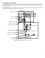
3.2 Description of Circuit Breaker Monitoring
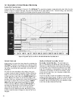
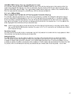
Typical Trip Trace Example
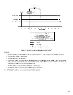
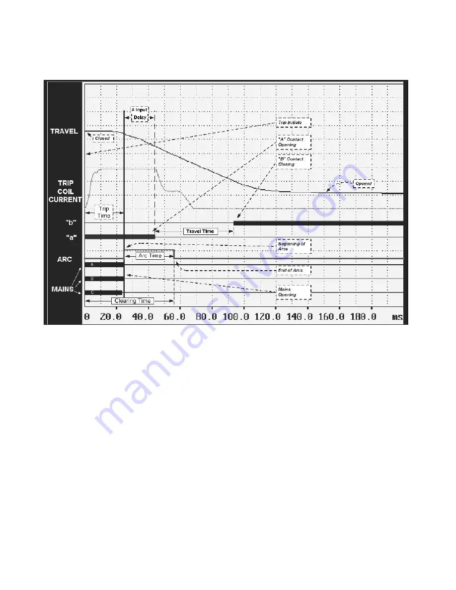
A typical trip trace is illustrated in Figure 6. The
OPTI
mizer
2
,
by examining signals corresponding the start of the trip (trip
initiate or the 52 / a contact opening), the end of mechanism travel (green light or 52 / b contact closing), and secondary
phase currents can obtain a wealth of information about the power circuit breaker.
Figure 6: Typical Trip Trace, with Arc Duration Information Superimposed
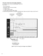
General Comments
Examination of a typical trip trace allows the quantities the
OPTI
mizer
2
records to be visualized. Arc duration (ARC),
although not possible to record during a de-energized trip
test using conventional test equipment, is shown here for
illustration.
The time line corresponding to the parting of the main
contacts (mains) is used to determine the time difference
between this event and either the trip initiate or the 52 / a
contact opening. In each case the
A INPUT DELAY
time
will be different. The choice to use the trip initiate or the
parting of the 52 / a will depend on where the OPTImizer’s
Aux A input is wired in the circuit. The proper
A INPUT
DELAY
must be programmed accordingly. The ability
to know this time difference allows the
OPTI
mizer
2
to
precisely start timing the arc for both the arc duration
record and the wear duty (I
2
x T or I x T) calculations.
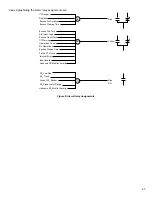
Reference for the following function descriptions in this
section should be made to Figure 6A, Typical Trip Trace
Diagram.
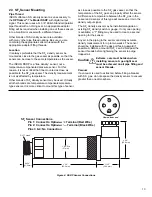
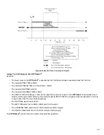
Interface to Breaker Secondary Current
Secondary Current Interface
- The per phase (
f
A,
f
B,
f
C) interrupting duty information and arc duration
information is ascertained by interfacing to the bushing
CT secondary current circuits using snap-on CT Pickup
Coils. The acquisition of interrupting current information
is therefore non-intrusive, as the CT secondary current
circuits do not have to be cut or otherwise modified. No
shunts are required.
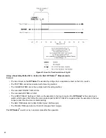
The CT secondary circuits are available at the breaker
cabinet and the control house, (if there is a control house).
The
Protective Relay Bushing CT’s
secondary circuits
should be used, since Metering CTs may saturate at high
current levels associated with fault duty.


