Serial Port Configuration
137
Software Configuration Guide, Revision 1.03
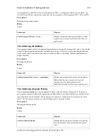
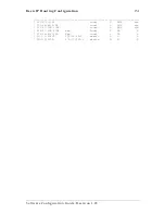
Port : serial 0 0 0
State : CLOSED
Hardware Port : X.21
Port Type : DTE
CRC Type : CRC-16
Max Frame Length: 2048
Recv Threshold : 1
Encapsulation : framerelay
16.7 Defining the Transmit Data Clock Edge
SmartWare allows defining the received clock edge on which data shall be transmitted over the serial
interface from a SmartNode to a peripheral device. The command
transmit-data-on-edge
, offers the
options
positive
or
negative
for this purpose. As default the positive edge is used if nothing is specified.
Procedure
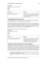
To set the the received clock edge on which data shall be transmitted over the serial interface
Mode
Port Serial
Command Purpose
Step 1
node
(prt-ser)[
slot
/
port
]#transmit-data-on-
edge {positive | negative}
Defines the received clock edge on
which data shall be transmitted over
the serial interface. The positive clock
edge is used as default setting if
nothing is specified.
Example: Configuring the
The following example shows how to define that data shall be transmitted on the negative received
clock edge on the serial interface on slot 0 and port 0 of a SmartNode 2300 series device.
SN(cfg)#
port serial 0 0
SN(prt-ser)[0/0]#
transmit-data-on-edge negative
16.8 Enter Frame Relay Mode
This Section describes the tasks for configuring Frame Relay for the serial interface on a SmartNode
series 2000 device, after setting the basic serial interface parameters according to the chapters above.
Procedure
To enter the Frame Relay configuration mode
Mode
Administrator execution
Command Purpose
Step 1
node
(cfg)#port serial
slot port
Selects the serial interface on slot and
port
Step 2
node
(prt-ser)[
slot
/
port
]#framerelay
Enters the Frame Relay configuration
mode
Summary of Contents for SmartWare R2.00
Page 2: ......

