51
sERVICINg
Ideal Logic Code Combi -
Installation and Servicing
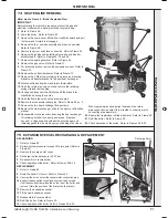
74 hEaT ENgINE RENEWaL
Refer also to Frame 6 - ‘Boiler Exploded View’
IMpORTaNT
Before starting the removal procedure, protect the gas and
electrical controls with a waterproof sheet or plastic bag.
1.
Refer to Frame 49.
2.
Drain the boiler. Refer to Frame 63.
3.
Remove the sump cover, lift the flue manifold upward and pull
the lower end forward to disengage.
4.
Remove the fan / venturi assembly and place on one side.
Refer to Frame 50.
5.
Remove the burner and place on one side. Refer to Frame 52.
6.
Remove the ignition and detection electrodes and divertor
actuator head. Refer to Frames 54, 55 and 58.
7.
Remove the spark generator. Refer to Frame 56.
8.
Remove the gas valve. Refer to Frame 57.
9.
For improved access remove the expansion vessel. Refer to
Frame 75.
10.
Remove the no flow thermistor. Refer to Frame 73.
11.
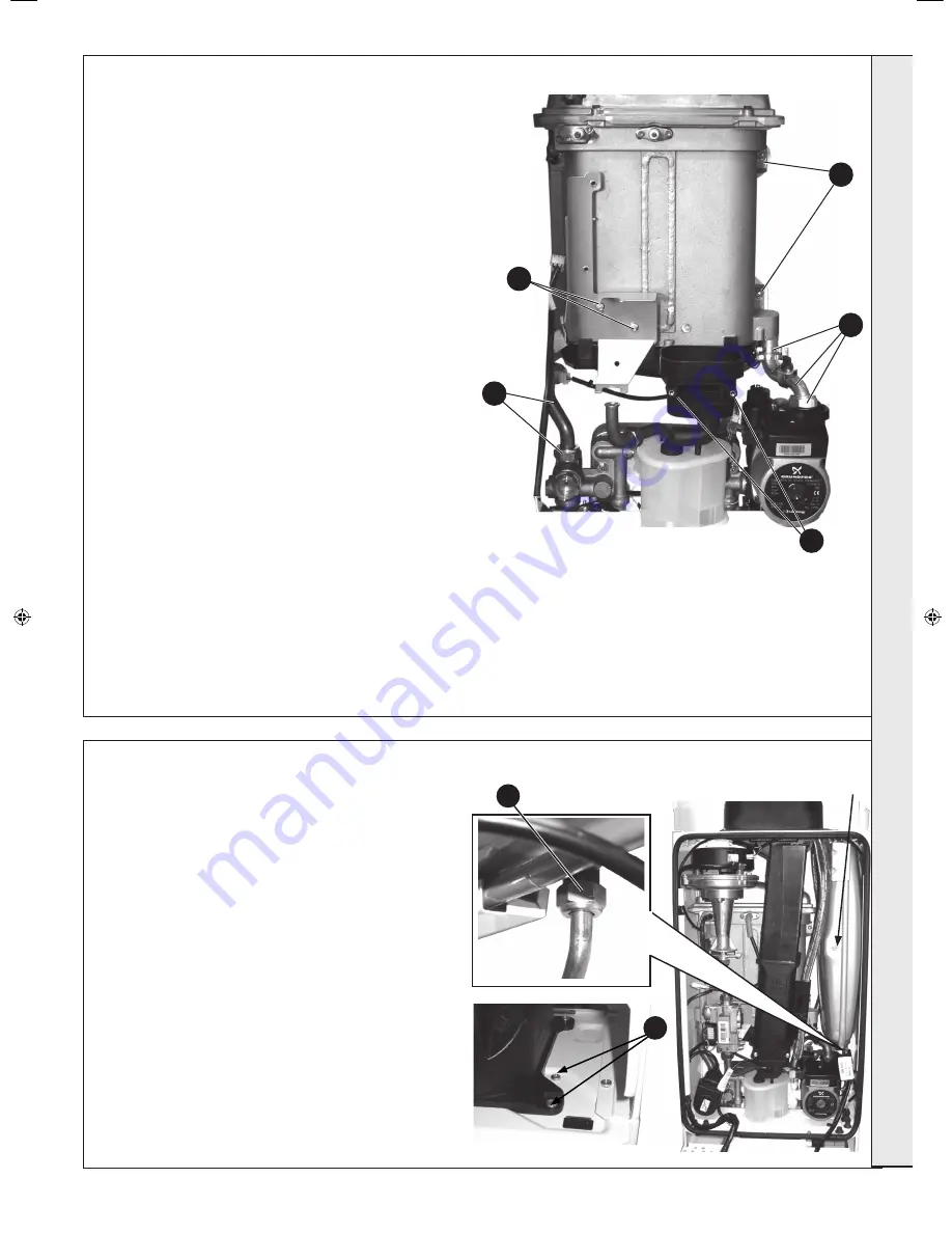
Remove the 2 M5 screws retaining the gas valve mounting
bracket and transfer bracket to the new heat exchanger.
12.
Disconnect leads from flow and return thermistors.
13.
Undo the return pipe union nut and remove the retaining
spring clip and remove pipe.
14.
Unclip and disconnect the DHW pipe off the brass inlet
manifold and swing to one side.
15.
Undo the flow pipe union nut and remove pipe.
16.
Remove the condensate rubber pipe. Refer to Frame 59, no. 2.
17.
Remove the two heat exchanger fixing screws.
18.
Remove the Heat exchanger, slide to the right out of location
bracket.
19.
Reassemble in reverse order, ensuring the heat exchanger
LH retaining bracket is correctly positioned. Replace
any new ‘o’ rings supplied with new heat exchanger and
replacing gaskets or seals if any sign of damage is evident.
17
13
15
11
When replacing the spring clips located on the return
pipe connection, ensure clip is oriented to correctly match
connecting pipe diameters.
20.
Ensure the trap/siphon is filled with water. Refer to Frame 59.
21.
Refill the boiler. Refer to Frame 30.
22.
Check operation of the boiler. Refer to Frames 38 & 39.
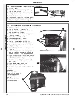
75 ExpaNsION VEssEL REChaRgINg & REpLaCEMENT
9
10
REChaRgINg
1.
Refer to Frame 49.
2.
Relieve system pressure through CH drain point (Refer to
Frame 63).
3.
Remove the charge point cover.
4.
Recharge the tank pressure to 0.75 bar.
5.
Re-assemble in reverse order
6.
Check operation of the boiler. Refer to Frames 38 & 39.
REpLaCEMENT
7.
Refer to Frame 49.
8.
Drain the boiler CH circuit. Refer to Frame 63.
9.
Unscrew the union nut on the vessel water connection pipe.
10.
Support the expansion vessel and unscrew the 2 screws
from the securing clamp, located on the top of the boiler, and
remove. (Note the position of the bracket on the vessel)
11.
Remove the expansion vessel.
12.
Fit the new expansion vessel.
13.
Reassemble in reverse order.
14.
Refill the boiler. Refer to Frame 30.
15.
Check operation of the boiler. Refer to Frames 38 & 39.
Recharge Point
3
s
ER
VICIN
g
206279-1.indd 51
06/01/2011 09:10:46
Summary of Contents for LOGIC Code Combi 26
Page 2: ...2 Ideal Logic Code Combi Installation and Servicing ...
Page 61: ......


