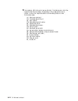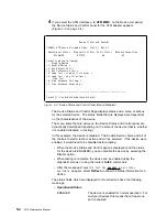
ENABLED PENDING
Waiting for completion of Enable request.
See Note
The device is in a special state that is explained
on the Page.
DISABLED
The device is Disabled. Diagnostic testing can
now be performed. For multi-port Devices this
means that all ports are disabled.
DISABLE PENDING
Waiting for completion of Disable request.
DIAGNOSTICS
A configured device is being used by the
diagnostics.
NOT CONFIGURED
The device is not configured for normal
operation.
MIS CONFIGURED
The configuration does not match the physical
device.
HARDWARE ERROR
A hardware error has been detected that
prevents further use of the device.
¹
Diagnostic Status
INACTIVE
Diagnostic for the device is not running.
TESTING
A testing process for the device is active and
the device is being tested.
LOOP AND LOG
A testing process for the device is active and
will loop and log any errors until stopped.
LOOP UNTIL ERROR
A testing process for the device is active and
will loop until an error occurs or it is stopped.
MESSAGE
A testing process for the device is active and it
is waiting for user input.
¹
Fault Status
OK
The last test of the device completed without
error.
ISOLATED
A hardware failure has been detected and
isolated to the device.
NON-ISOLATED
A problem has been detected, but the failure
may be external to the device. This most often
occurs with network adapters that have external
cables, modems, or LAN connections. Running
a diagnostic of the adapter with a wrap plug
attached can usually determine if the adapter
has failed.
UNKNOWN
No test results are currently available for the
device.
Chapter 5. Using Operational Diagnostics
5-5
Summary of Contents for Nways 2216
Page 1: ...2216 Nways Multiaccess Connector ÉÂÔ Service and Maintenance Manual SY27 0350 02 ...
Page 2: ......
Page 3: ...2216 Nways Multiaccess Connector ÉÂÔ Service and Maintenance Manual SY27 0350 02 ...
Page 8: ...vi 2216 Maintenance Manual ...
Page 10: ...Common Tasks and the IBM 2216 Library viii 2216 Maintenance Manual ...
Page 45: ...6 Remove the adapter from its location Chapter 2 Removal and Replacement Procedures 2 15 ...
Page 60: ...3 6 2216 Maintenance Manual ...
Page 84: ...4 24 2216 Maintenance Manual ...
Page 104: ...A 2 2216 Maintenance Manual ...
Page 106: ...Assembly 1 Final Assembly 2216 Model 400 B 2 2216 Maintenance Manual ...
Page 110: ...B 6 2216 Maintenance Manual ...
Page 114: ...1 2 3 4 5 6 7 8 9 10 Figure C 1 Power Cord Plugs by Country C 4 2216 Maintenance Manual ...
Page 138: ...F 12 2216 Maintenance Manual ...
Page 164: ......
Page 167: ......

