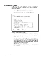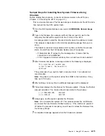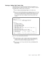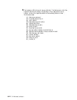
4
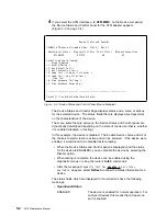
If you select the ATM interface (
<
2. ATM MMF
>
on the Device List panel),
the Device Status and Control panel for the ATM adapter appears
(Figure 5-3 on page 5-4).
@
Device Status and Control
155Mb/s ATM over multi-mode fiber, Slot 2,- Net # 1
Operational Status
Diagnostic Status
Fault Status
Network Connection
DISABLED
ACTIVE
OK
UP
Select from the following:
Disable Device
<1. Enable Device >
<2. Run Default Test >
<3. Run Interactive test >
<4. Loop Test - stop on first error >
<5. Loop Test - Log all errors >
Stop Test
<6. View Hardware Test Log >
<7. View Hardware Error Log >
----------------------------------------------------------------
Select (1-7 or B=Back R=Refresh H=Help):
Figure
5-3. Device Status and Control Panel (Device Disabled)
The Device Status and Control Page displays status and a menu of actions
for the selected device. The status fields that are displayed are dependent
on the characteristics of the device.
The menu items that are active on the Device Status and Control panel are
dynamically determined depending on the state of the device (that is, whether
it is enabled, disabled, or testing).
In this example, the device is disabled. The Enable Device choice and all of
the choices to start a test are active and can be selected. If the device were
enabled, it would need to be disabled before testing.
¹
When the Device Status and Control panel is displayed (and the status
for the device is ENABLED), you can disable the device by selecting the
Disable option.
¹
When testing is complete, the device can be enabled using the
diagnostic menus or using the router’s talk 5 commands.
¹
After the message
Diagnostic Test for adapter_x has status
available
appears, select Refresh to show the status information for a
device.
The status fields which are displayed for most devices have the following
meanings:
¹
Operational Status
ENABLED
The device is enabled for normal operation. For
multi-port devices this means that at least one
port is enabled.
5-4
2216 Maintenance Manual
Summary of Contents for Nways 2216
Page 1: ...2216 Nways Multiaccess Connector ÉÂÔ Service and Maintenance Manual SY27 0350 02 ...
Page 2: ......
Page 3: ...2216 Nways Multiaccess Connector ÉÂÔ Service and Maintenance Manual SY27 0350 02 ...
Page 8: ...vi 2216 Maintenance Manual ...
Page 10: ...Common Tasks and the IBM 2216 Library viii 2216 Maintenance Manual ...
Page 45: ...6 Remove the adapter from its location Chapter 2 Removal and Replacement Procedures 2 15 ...
Page 60: ...3 6 2216 Maintenance Manual ...
Page 84: ...4 24 2216 Maintenance Manual ...
Page 104: ...A 2 2216 Maintenance Manual ...
Page 106: ...Assembly 1 Final Assembly 2216 Model 400 B 2 2216 Maintenance Manual ...
Page 110: ...B 6 2216 Maintenance Manual ...
Page 114: ...1 2 3 4 5 6 7 8 9 10 Figure C 1 Power Cord Plugs by Country C 4 2216 Maintenance Manual ...
Page 138: ...F 12 2216 Maintenance Manual ...
Page 164: ......
Page 167: ......

