


Back Backplane Assembly
|
Note for Models 010 and 500: The back backplane assembly can be removed while
the disk drive modules at the front of the 7133 remain operational. Unless you have a
particular reason to do so, do not turn off the using system or the 7133 when removing or
installing the back backplane assembly.
|
1
Use the Link Verification service aid (see the chapter about SSA service aids in the
|
SSA Adapters: User’s Guide and Maintenance Information manual) to ensure that all
SSA loops that pass through the front backplane assembly are not broken. (For
example, all external SSA cables are connected correctly; all disk drive modules
and, if required, dummy disk drive modules are installed correctly.)
If a loop is broken, repair it, then check whether you have solved the original
problem. If the problem remains, go to step 2.
|
2
If not already done, remove (Models 010 and 020) or open (Models 500 and 600)
|
the front cover (see “Covers” on page 3-2).
|
3
On Models 010 and 500, ensure that the disk drive modules in the back of the 7133
|
are no longer available to the using system.
|
On Models 020 and 600, stop all operations on the 7133, then remove all power
|
from the 7133 (see “All Power” on page 3-7).
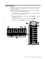
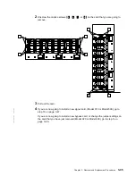
4
Remove the two back-power cards from the front of the 7133 (see “Back-Power
Cards” on page 3-41).
|
5
On Models 500 and 600, open the back cover (see “Back Cover (Models 500 and
|
600 Only)” on page 3-6).
|
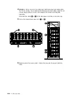
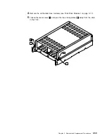
6
Carefully make a note of the locations of the disk drive modules and (if present)
|
dummy disk drive modules that are at the back of the 7133. This action ensures
|
that you reinstall the modules into their original slots. (They might not all be
|
connected to the same SSA loop.) Attach identifying labels to the modules if you
|
want to.
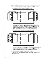
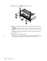
7
Remove all the disk drive modules and dummy disk drive modules from the back of
the 7133 (see “Removing a Module” on page 3-17).
|
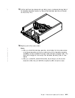
8
At the back of the 7133, do the following actions:
|
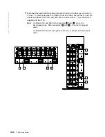
For Models 010 and 500:
|
a. Disconnect the external SSA cables (if present) from the two back-signal
|
cards. To prevent damage to the SSA connector screws, ensure that you
|
use the special screwdriver (SSA tool, part 32H7059) to unscrew them. The
|
screwdriver is supplied with the 7133.
|
b. Remove the two back-signal cards (see “Signal Cards and Bypass Cards”
|
on page 3-43).
|
For Models 020 and 600:
|
a. Disconnect the external SSA cables (if present) from all four bypass cards.
|
To prevent damage to the SSA connector screws, ensure that you use the
|
special screwdriver (SSA tool, part 32H7059) to unscrew them. The
|
screwdriver is supplied with the 7133.
3-52
7133 Service Guide
Summary of Contents for 7133 Series
Page 1: ...7133 SSA Disk Subsystems Service Guide SY33 0185 02...
Page 2: ......
Page 3: ...7133 SSA Disk Subsystems Service Guide SY33 0185 02...
Page 8: ...vi 7133 Service Guide...
Page 14: ...xii 7133 Service Guide...
Page 44: ...Labels Dummy Fan and Power Supply Assembly 1 30 7133 Service Guide...
Page 94: ...2 10 7133 Service Guide...
Page 110: ...2 2021 6 7133 Service Guide...
Page 114: ...2 2022 4 7133 Service Guide...
Page 138: ...2 2330 18 7133 Service Guide...
Page 146: ...2 16 7133 Service Guide...
Page 210: ...3 64 7133 Service Guide...
Page 222: ...4 12 7133 Service Guide...
Page 229: ......
Page 230: ...Part Number 32H6990 Printed in the United Kingdom 32H699 SY33 185 2...


