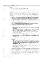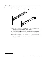
|
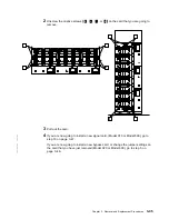
b. Remove the four bypass cards (see “Signal Cards and Bypass Cards” on
|
page 3-43).
|
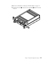
9
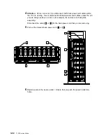
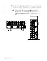
Reach into the back of the 7133. Unscrew the four captive screws
1
, and remove
|
the bracket assembly
2
.
|
Note: The diagrams in these instructions represent 7133 Models 010 and 020.
|
The procedure for Models 500 and 600 is the same, except that everything is turned
|
through 90 degrees.
|
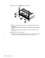
10
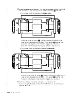
If you are servicing a Model 020 or 600, remove the two self-adhesive plastic air
|
baffles
4
. You will need to install two new plastic air baffles (part 31H8722) after
|
you have replaced the backplane assembly.
11
Unscrew the four captive screws
3
.
Chapter 3. Removal and Replacement Procedures
3-53
Summary of Contents for 7133 Series
Page 1: ...7133 SSA Disk Subsystems Service Guide SY33 0185 02...
Page 2: ......
Page 3: ...7133 SSA Disk Subsystems Service Guide SY33 0185 02...
Page 8: ...vi 7133 Service Guide...
Page 14: ...xii 7133 Service Guide...
Page 44: ...Labels Dummy Fan and Power Supply Assembly 1 30 7133 Service Guide...
Page 94: ...2 10 7133 Service Guide...
Page 110: ...2 2021 6 7133 Service Guide...
Page 114: ...2 2022 4 7133 Service Guide...
Page 138: ...2 2330 18 7133 Service Guide...
Page 146: ...2 16 7133 Service Guide...
Page 210: ...3 64 7133 Service Guide...
Page 222: ...4 12 7133 Service Guide...
Page 229: ......
Page 230: ...Part Number 32H6990 Printed in the United Kingdom 32H699 SY33 185 2...


