|
7
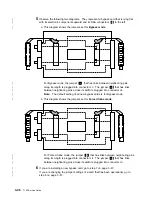
Check whether the jumpers on the new card are set for the same mode as are the
|
jumpers on the card that you have just removed.
|
If they are set for the same mode, you can now install the new bypass card. Go to
|
step 10.
|
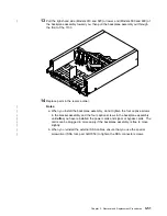
If they are not set for the same mode, you must swap the positions of the jumpers
|
on the new card. Go to step 8.
|
8
Unplug the jumpers from their connectors.
|
9
Swap the positions of the jumpers to change to the other mode (see steps 5a and
|
5b), then go to step 10.
10
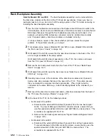
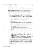
Replace parts in the reverse order. Ensure that you push the cards fully home.
|
Note: When you reinstall the external SSA cables, ensure that you use the special
|
screwdriver (SSA tool, part 32H7059) to tighten the SSA connector screws.
Chapter 3. Removal and Replacement Procedures
3-47
Summary of Contents for 7133 Series
Page 1: ...7133 SSA Disk Subsystems Service Guide SY33 0185 02...
Page 2: ......
Page 3: ...7133 SSA Disk Subsystems Service Guide SY33 0185 02...
Page 8: ...vi 7133 Service Guide...
Page 14: ...xii 7133 Service Guide...
Page 44: ...Labels Dummy Fan and Power Supply Assembly 1 30 7133 Service Guide...
Page 94: ...2 10 7133 Service Guide...
Page 110: ...2 2021 6 7133 Service Guide...
Page 114: ...2 2022 4 7133 Service Guide...
Page 138: ...2 2330 18 7133 Service Guide...
Page 146: ...2 16 7133 Service Guide...
Page 210: ...3 64 7133 Service Guide...
Page 222: ...4 12 7133 Service Guide...
Page 229: ......
Page 230: ...Part Number 32H6990 Printed in the United Kingdom 32H699 SY33 185 2...


