13. How to Reset an
Absolute Encoder
291
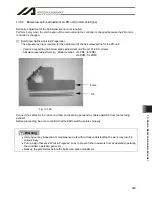
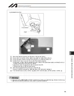
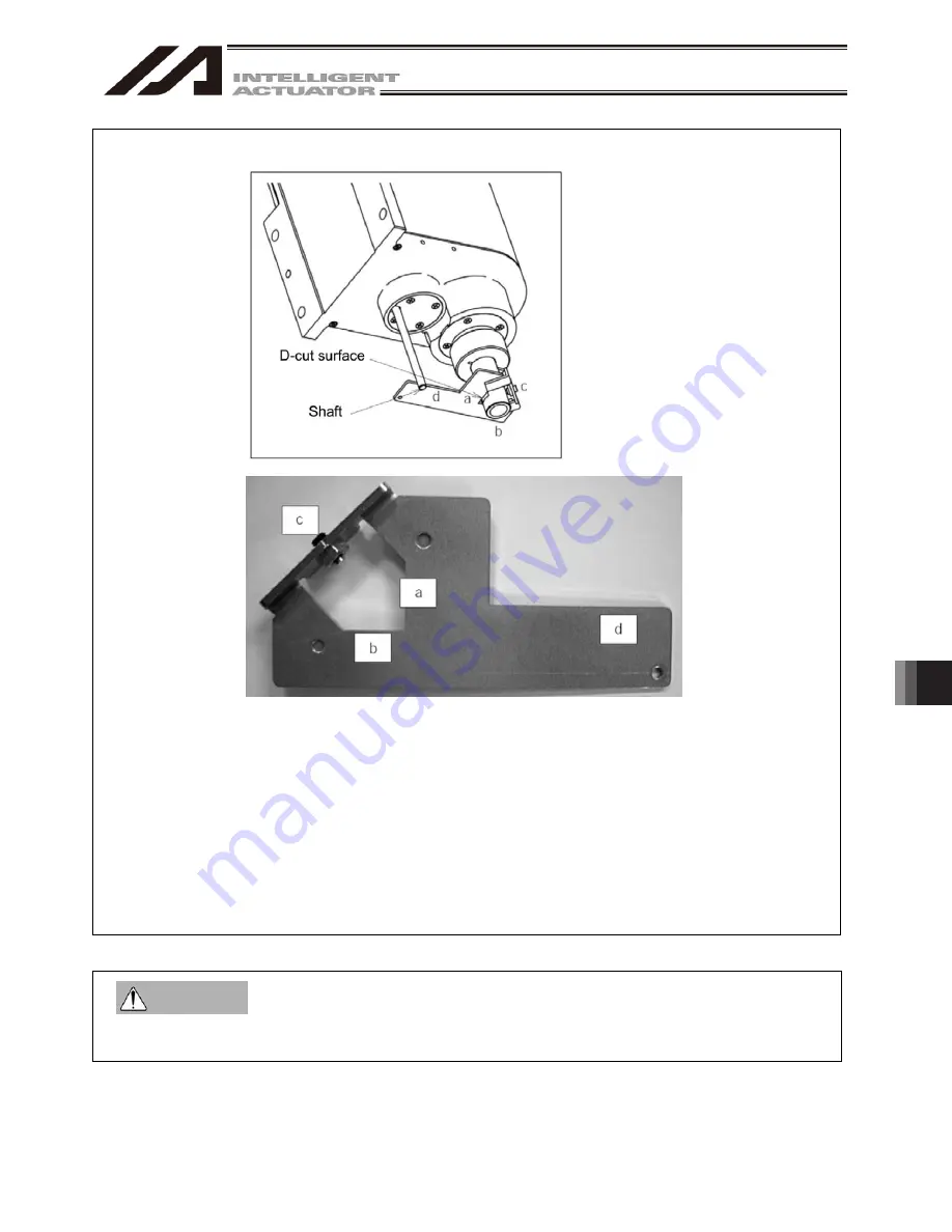
Jig Installation method
[1] Insert the ball-screw spline into the hole in the jig from below.
[2] Cause the D-cut surface of the ball-screw spline to contact the surface a.
[3] Cause the side surface of the ball-screw spline to contact the surface b.
[4] Tighten the screw c to secure the jig onto the ball-screw spline.
* At this time, confirm that the adjustment jig is vertical to the ball-screw spline and that the D-cut
surface and surface a are firmly in contact.
* Applicable screw: Hexagonal socket head setscrew M5
* Tightening torque: 20 [N
cm] (reference)
[5] Insert the supplied shaft into the hole in the ZR unit.
* Exercise caution because the shaft will come off if the hand is released.
[6] Turn the ball-screw spline until the supplied shaft contacts lightly with the surface d of the jig.
Always press the EMERGENCY STOP switch before setting an adjustment jig. Failure to do so may
cause the actuator to malfunction and result in a serious accident.
Warning
Summary of Contents for IA-101-X-MW
Page 2: ......
Page 4: ......
Page 8: ......
Page 50: ...1 Before You Begin 42 1 4 Connection to Controller Fig 1 48 X SEL K J Type Controller...
Page 52: ...1 Before You Begin 44 Figure shows example of TT Fig 1 50 Table Top Actuator TT TTA...
Page 53: ...1 Before You Begin 45 Fig 1 51 X SEL KX JX Type Controller...
Page 62: ...1 Before You Begin 54 Fig 1 60 ASEL Type Controller USB Cable...
Page 63: ...1 Before You Begin 55 Fig 1 61 PSEL Type Controller USB Cable...
Page 189: ...9 Symbol Edit Window 181...
Page 251: ...13 How to Reset an Absolute Encoder 243 Fig 13 38 Arm Length 120 Reference Position...
Page 386: ...16 Appendix 378...
Page 391: ......


