10. Coordinate System Definition Data Edit W
indow
190
(2) Positioning based on tool coordinate system offsets
Perform positioning after selecting a desired tool coordinate system.
Use the SLTL instruction to select a desired tool coordinate system No. in the SEL program.
Once set, the tool coordinate system selection No. will remain effective after the program ends, and even
after the power is reconnected if the system memory backup battery is installed.
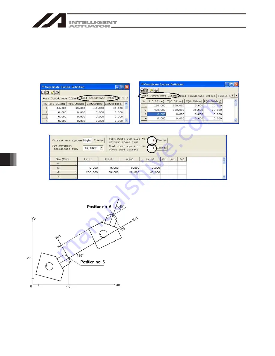
[1] When performing PTP positioning of the tool end in tool coordinate system No. 1 to position No. 5
and No. 6 in work coordinate system No. 1:
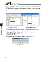
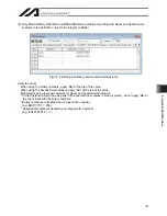
Fig. 10.9 Tool Coordinate System Offset Setting Screen Fig. 10.10 Work Coordinate System Offset Setting Screen
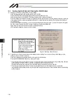
Fig. 10.11 Position Data Screen:
Work Coordinate System No. 1 and Tool Coordinate System No. 1 Setting
Sample program
:
:
SLWK 1 Select work coordinate system No. 1.
SLTL 1 Select tool coordinate system No. 1.
PTPR
Specify right arm as the PTP target
arm.
MOVP 5 Move to position No. 5.
MOVP 6 Move to position No. 6.
:
:
:
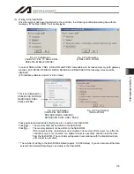
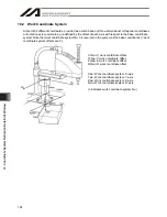
The Z-axis position at the tool end is as follows:
Position No. 5 Zb = 0
Position No. 6 Zb = 20
A top view is shown at the left.
Summary of Contents for IA-101-X-MW
Page 2: ......
Page 4: ......
Page 8: ......
Page 50: ...1 Before You Begin 42 1 4 Connection to Controller Fig 1 48 X SEL K J Type Controller...
Page 52: ...1 Before You Begin 44 Figure shows example of TT Fig 1 50 Table Top Actuator TT TTA...
Page 53: ...1 Before You Begin 45 Fig 1 51 X SEL KX JX Type Controller...
Page 62: ...1 Before You Begin 54 Fig 1 60 ASEL Type Controller USB Cable...
Page 63: ...1 Before You Begin 55 Fig 1 61 PSEL Type Controller USB Cable...
Page 189: ...9 Symbol Edit Window 181...
Page 251: ...13 How to Reset an Absolute Encoder 243 Fig 13 38 Arm Length 120 Reference Position...
Page 386: ...16 Appendix 378...
Page 391: ......

