13. How to Reset an
Absolute Encoder
225
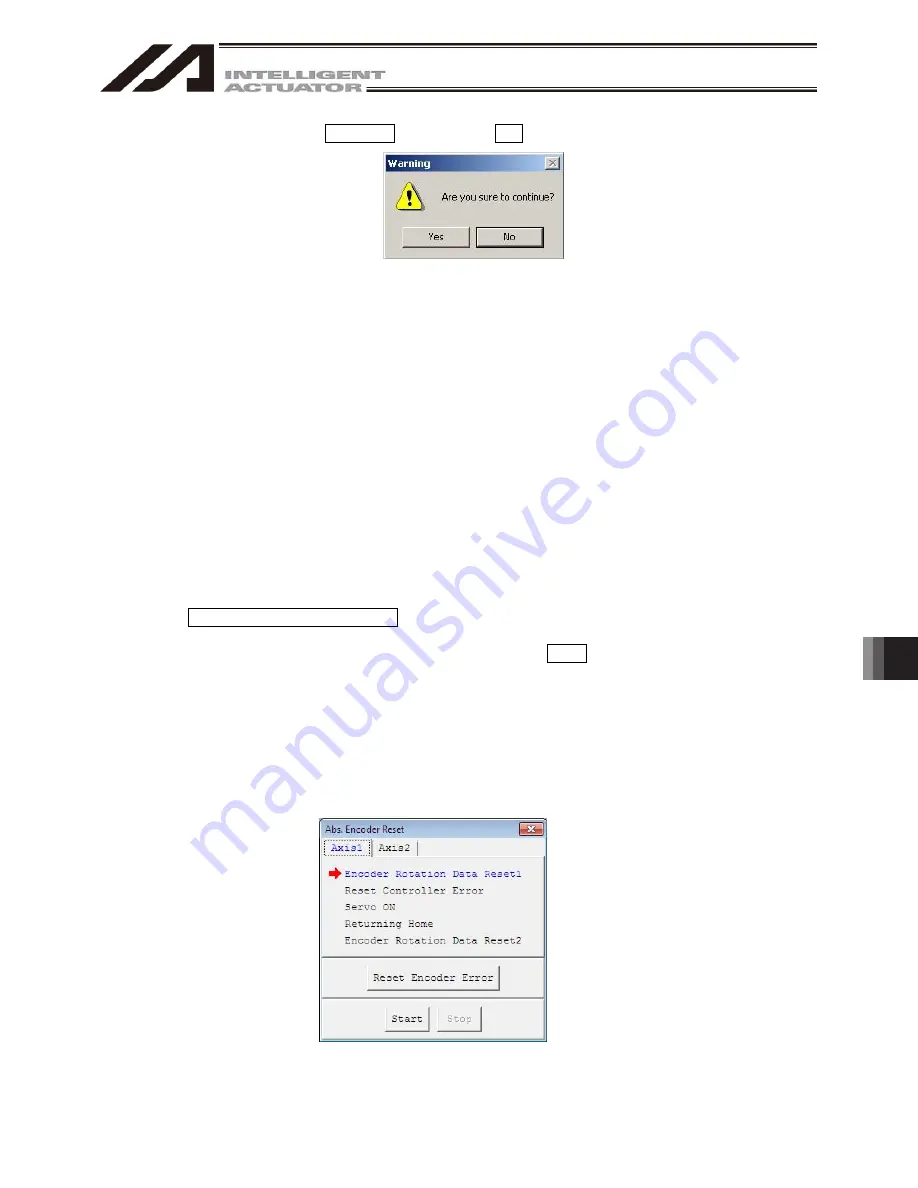
(5) When the following ‘Warning’ dialog box appears, click Yes
Fig. 13.4 Warning
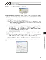
(6) After the Encoder Rotation Data Reset 1 process is completed, the red arrow will move to the next item
below. Click the applicable button. Repeat this operation until all of the following processes are completed
(every time a process is completed, the red arrow will move to the next item below):
1) Reset Controller Error
2) Servo ON
3) Returning Home
4) Servo OFF (Not necessary for Version 1.1.0.0 and later)
(Note 1)
Note 1: If you are using PC software of version 1.1.0.0 or later and a driver with CPU version 0.23 or
later, the Encoder Rotation Data Reset 2 process is performed with the servo ON. Accordingly,
the servo OFF step is skipped.
5) Encoder Rotation Data Reset 2
(Note) With an earlier product, clicking Reset Controller Error may generate an error (No. D10: IPM
error). If this error occurs, close the PC tool, reconnect the controller power, and then repeat from
step (2). (If the encoder battery is normal, the error will no longer occur after the power is
reconnected and “rdy” or “Ardy” will be shown on the controller’s 7-segment display. Take note
that the axis has not yet completed homing in this state).
After the Encoder Rotation Data Reset 2 process is completed, the red arrow will return to the position in
(3). If you want to perform an absolute encoder reset for multiple axes, select each subsequent target axis
and repeat the steps from (3). To end the reset operation, click Close to close the Abs. Encoder Reset
dialog box.
(Note) If a need arises to perform an absolute encoder reset for multiple axes, be sure to complete steps
(3) through (6) for all applicable axes before performing a software reset in step (7).
* (7) [Absolute Reset] window appears for Main Application: SSEL V0.57 or later, ASEL V0.45 or later,
V12.02.05.00.
(7)
[Absolute Reset] window will show up. Select the tab for the axis that rewuires the absolute reset.
Fig. 13.5 Absolute Reset Window
Summary of Contents for IA-101-X-MW
Page 2: ......
Page 4: ......
Page 8: ......
Page 50: ...1 Before You Begin 42 1 4 Connection to Controller Fig 1 48 X SEL K J Type Controller...
Page 52: ...1 Before You Begin 44 Figure shows example of TT Fig 1 50 Table Top Actuator TT TTA...
Page 53: ...1 Before You Begin 45 Fig 1 51 X SEL KX JX Type Controller...
Page 62: ...1 Before You Begin 54 Fig 1 60 ASEL Type Controller USB Cable...
Page 63: ...1 Before You Begin 55 Fig 1 61 PSEL Type Controller USB Cable...
Page 189: ...9 Symbol Edit Window 181...
Page 251: ...13 How to Reset an Absolute Encoder 243 Fig 13 38 Arm Length 120 Reference Position...
Page 386: ...16 Appendix 378...
Page 391: ......


