43
fi
g. 2.1
fi
g. 2.2
fi
g. 2.3
fi
g. 2.4
fi
g. 2.5
fi
fifi
fi
fi
A
A
B
C
3
2
1
B
fi
C
2 - S
ਠਥਤਲ਼ਸ
D
ਤਵਨਢਤਲ
Emergency Descent Control System
1-
Make sure the engine is shut down. On an
F300 unit model used in a linked
confi guration
, make sure that both engines are shut down.
2-
Before using the emergency descent control system check the hydraulic oil level to
make sure it is in the
FULL
range on the dipstick. The emergency descent system
must
not be used if there is a major hydraulic leak
. On an
F300 unit model used in a
linked confi guration
, make sure to verify both sides of the unit.
3-
Perform a visual inspection of gears, pinions and rollers and other parts of the structure
to make sure that they are clear of debris and that there are no signs of damages that
could prevent the emergency descent system from operating normally. The emergency
descent system
must not be used if the gear system is damaged
. In case of doubt,
contact a qualifi ed technician to seek advice. For the defi nition of a qualifi ed technician,
refer to p. 7 of the
Performance and Safety Rules
section.
4-
Pull the emergency stop button to power on the control panel and log in. On an
F300
unit model used in a linked confi guration
, power on both control panels.
5-
Review all screen alerts and make sure that there is no high oil temperature alert
displayed. Make sure also that the overspeed safety device is not engaged. For more
information about the control panel and the alerts displayed, refer to the
Control Panel
section, on p. 74. On an
F300 unit model used in a linked confi guration
, perform
this step on both sides of the unit.
6-
If there is a high oil temperature alert on the screen or if high oil temperature is suspected,
let the oil cool down suffi ciently before initiating the emergency descent procedure.
Emergency descent procedure for a single unit installation
Safety Devices
In the event of an engine failure, a shortage of gasoline (for gas-powered units), a power
outage (for electrical units) or broken parts, use the gravity-activated emergency descent
control system to bring the motorized unit safely down to the nearest safe evacuation
point. It is important to note that the emergency descent system must not be used in the
event of damages to a gear box, an overspeed safety device, a gear, an idler or if there
is a major hydraulic leak.
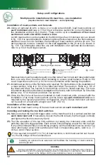
Location of emergency descent
control valve levers and manual
pump
Control valve levers
Knob on manual pump relief valve
Manual pump
WARNING
If the
emergency descent must be interrupted
, open the manual pump relief
valve by turning the knob
counterclockwise
or lift the upper control valve lever
(“3”, in fi g. 2.2) to release the hydraulic pressure. On an F300 unit model used in
a
linked confi guration
, this step can be performed on either side of the mast.
In a multiple units confi guration, immediately stop the descent of the unit at the
operating end of the bearing structure.
WARNING
The F2 Series emergency descent system must not be used in the event of damages to a gear
box, a brake, an overspeed safety device, an idler or if there is a major hydraulic leak.


