118
fi
g. 8.40
fi
g. 8.41
fi
g. 8.42
8 - A
ਢਢਤਲਲਮਨਤਲ
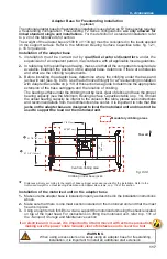
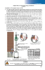
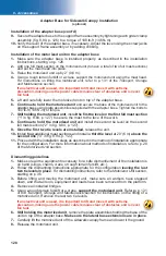
The F2 Series base is assembled with 3/4" bolt assemblies while the adapter base for
freestanding installation is assembled with 1" bolt assemblies (8). It is recommended to have
the appropriate tools at hand when removing the lateral base extensions and assembling the
adapter base for freestanding installations.
1" (
GR8
) bolts
and lock
washers (2 per
plate)
1" (
GR8
) nuts
fi
g 8 42
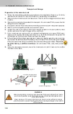
Authorized Height for a Freestanding Installation with Adapter Base
Authorized Height for a Freestanding Installation with Adapter Base
Ref
Length of base outrigger
extension
Maximum height of mast
Maximum number of planks
A
10" (25 cm)
28' (8,5 m)
3
B
20" (51 cm)
38' (11,6 m)
3
C
30" (76 cm)
48' (14,6 m)
3
A
B
C
A
B
C
To wall
Back
Front
Adapter Base for Freestanding Installation
(optional)
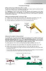
Installation of the motorized unit on the adapter base (cont’d)
4-
Remove the 3/4" bolt assemblies to take away both lateral extensions from the base of
the motorized unit.
5-
Lift the motorized unit and carefully lower it on the adapter base for freestanding installation,
making sure to align it properly.
6- Still holding the motorized unit
, raise the unit until it is halfway up the second mast
section.
7-
Secure the base of the motorized unit to the adapter base using the 1" (
GR8
) bolt
assemblies (8) supplied with the plates on the adapter base. Tighten the bolts to
100 lb-ft (136 N-m) of torque.
8-
Once the base is secured, release the motorized unit.
9-
Proceed with the installation of the unit by following the instructions for a standard single
unit confi guration starting on p. 20 of the
Motorized Unit
section. Make sure that the
outriggers on the adapter base are extended according to the height of the mast, as is
required and allowed. Refer to the
Authorized Height of Freestanding Installation
table
(fi g. 8.42) as a guide for the appropriate extension of the outriggers
.
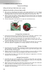
Regular base
Adapter base


