111
fi
g. 8.15
fi
g. 8.16
fi
g. 8.17
8 - A
ਢਢਤਲਲਮਨਤਲ
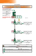
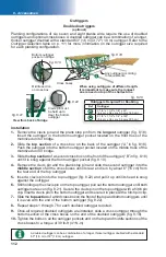
Outriggers can be installed on two levels on F2 Series motorized units and bridges, top and
bottom. Plank support outriggers are not designed to support the weight of material.
Plank support outriggers must be installed no more than 5' (1,5 m) from one another.
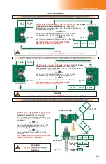
The size and number of outriggers required will vary according to the planking confi guration.
Planking confi gurations of four to eight planks will require the use of additional, optional
components such as thicker or longer outriggers and cross boxes. Refer to the
Outrigger
Selection
table (fi g. 8.15) for more information about the size and number of outriggers
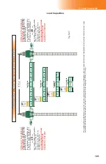
required for each planking confi guration. Refer also to p. 112 for more information on the
installation and use of doubled outriggers.
For any outrigger confi guration other than those described in this owner’s manual, contact
the distributor/service center.
Outriggers
Outrigger Selection
Planking confi guration Outrigger size
3 planks
(standard confi guration)
2 1/2” x 1 1/2” x 1/8” x 63”
(6,4 cm x 3,8 cm x 0,3 cm x 160 cm)
(standard outrigger, as provided with unit
or bridge)
SINGLE
4 planks
2 1/2” x 1 1/2” x 3/16” x 72”
(6,4 cm x 3,8 cm x 0,5 cm x 183 cm)
SINGLE
5 planks
2 1/2” x 1 1/2” x 1/4” x 84”
(6,4 cm x 3,8 cm x 0,6 cm x 213 cm)
SINGLE
6 planks
2 1/2” x 1 1/2” x 1/4” x 120”
(6,4 cm x 3,8 cm x 0,6 cm x 305 cm)
DOUBLED
7 planks
2 1/2” x 1 1/2” x 1/4” x 120”
(6,4 cm x 3,8 cm x 0,6 cm x 305 cm)
DOUBLED
8 planks
2 1/2” x 1 1/2” x 1/4” x 120”
(6,4 cm x 3,8 cm x 0,6 cm x 305 cm)
DOUBLED
Planking confi gurations
Planking confi guration guidelines
fi
g 8 16
Planking confi guration – width allowed on installation
Planking confi guration – width allowed on installation
Number of planks
Motorized unit
Bearing bridge
Cantilever(s)
0 to 3 planks
100% of total width
100% of total width
100% of total width
4 to 8 planks
100% of total width
50% of total width
Max width 5' (1,5 m)
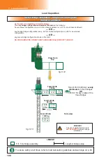
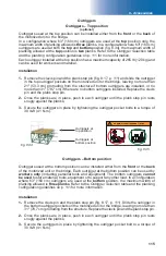
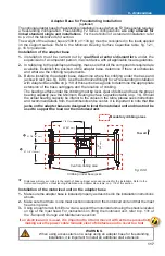
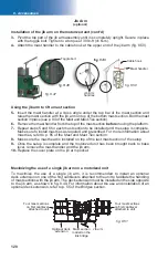
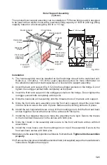
Plank stop pin
Hitch pin clip
Clevis pin and
hitch pin clip


