130
fi
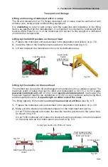
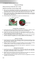
g. 9.1
fi
g. 9.2
fi
g. 9.4
fi
g. 9.3
fi
g. 9.3
9 - T
ਠਭਲਯਮਲ਼
, S
ਲ਼ਮਠਦਤ
ਠਭਣ
M
ਠਨਭਲ਼ਤਭਠਭਢਤ
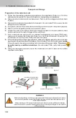
Location of bottom limit
switch trigger
Location of gas lever
Buff ers on base
1-
Follow the dismantling guidelines appropriate to the installation. Refer to p. 36 of the
Motorized Unit
section for more information on dismantling an installation.
2-
Make sure the motorized unit is at base level. Push in all the outriggers and lock them
in place.
3-
Secure all motorized unit guardrails for transport. On unit model F300, secure the link
bridge doors for transport.
4-
If required, remove the access stairs and railings and store each component properly.
5-
Make sure that all plastic panels are secured in place.
6-
Loosen the bolt of the bottom limit switch trigger located on the last (bottom) mast
section and lower the switch trigger all the way down.
7-
If the motorized unit was used in an unlinked confi guration (unit model F300 only),
make sure to replace the trolley link. Refer to p. 34 of the
Motorized Unit
section for
instructions on how to put the trolley link back into place.
8-
If the unit used in the setup is gas-powered, make sure that the gasoline valve lever has
been turned off and disconnect the battery. On unit model F300, verify both power packs.
If the unit used in the setup is electrical unit, disconnect the power cable.
This must
be performed by a certifi ed electrician.
On unit model F300, verify both power
packs.
9-
Using the emergency descent, lower the motorized unit until it rests on the buff ers
mounted on the base.
Preparation of the motorized unit
Transport and Storage
ck
ck
s
s
s
t
t
t
t
t
t
t
t
r
r
r
r
r
r
r
r
k
k
k
k
s.
s.
s.
s.
s.
s.
s.
s.
s
s
WARNING
Before transporting or storing a gas-powered F2 Series motorized unit, make
sure that all gasoline levers have been turned off and that all batteries have
been disconnected.
When storing an F2 Series motorized unit, there must be suffi cient cribbing
under the base to prevent freezing water from causing damages to the bottom
of the structure.


